Understanding the voltage transfer characteristic is fundamental for any engineer working with operational amplifiers (op-amps). This characteristic, often visualized using a graph, reveals the relationship between input and output voltages, a crucial element for circuit analysis and design. Specifically, the saturation regions of this characteristic dictate performance limitations. Furthermore, software tools like SPICE simulators allow engineers to model and analyze the voltage transfer characteristic of complex circuits efficiently. Analog Devices, a leading manufacturer of electronic components, provides extensive resources and documentation related to the voltage transfer characteristic of their op-amps.
Understanding the Voltage Transfer Characteristic (VTC)
The voltage transfer characteristic (VTC) is a fundamental concept in electronics, describing how the output voltage of a circuit changes in response to variations in its input voltage. This article provides a simplified explanation of VTCs, focusing on their importance and application in various electronic circuits.
What is a Voltage Transfer Characteristic?
At its core, the voltage transfer characteristic is a graphical representation – a plot – that illustrates the relationship between the input voltage (Vin) and the output voltage (Vout) of a circuit. Think of it as a roadmap showing you exactly what output you can expect for any given input.
- Input Voltage (Vin): The voltage applied to the input of the circuit. Conventionally plotted on the x-axis.
- Output Voltage (Vout): The resulting voltage at the output of the circuit, determined by the input voltage and the circuit’s properties. Conventionally plotted on the y-axis.
This graph allows engineers and hobbyists alike to quickly understand the behavior of a circuit and predict its performance under different operating conditions.
Why is the Voltage Transfer Characteristic Important?
The VTC is invaluable for several reasons:
- Circuit Analysis: It provides a visual representation of the circuit’s gain, linearity, and operating regions.
- Circuit Design: Engineers use VTCs to design circuits with specific output requirements for given input signals.
- Troubleshooting: By comparing the measured VTC to the expected VTC, one can identify potential faults or problems within the circuit.
- Amplifier Performance: VTCs are crucial for understanding and characterizing amplifiers, especially their gain and saturation behavior.
- Digital Logic: In digital circuits, the VTC defines the logic levels (high and low) and the transition region between them, which is critical for reliable operation.
Key Regions of a Voltage Transfer Characteristic
A typical VTC can be divided into distinct regions, each revealing different aspects of the circuit’s behavior. Consider the VTC of a simple inverter as an example to illustrate these regions.
Cut-off Region
In this region, a low input voltage results in a consistently high output voltage.
- Essentially, the circuit is "off," preventing current flow and maintaining a stable high output.
- In an inverter’s VTC, this region is usually located on the left side of the graph, where Vin is close to 0V.
Linear Region
This is the region where the output voltage changes most dramatically in response to changes in the input voltage.
- This is where the circuit exhibits the highest gain or amplification.
- The slope of the VTC in this region represents the gain of the circuit.
- For an inverter, the linear region is the transition area between the high and low output voltage levels.
Saturation Region
Here, a high input voltage causes the output voltage to become consistently low.
- The circuit becomes "saturated," and further increases in input voltage have little to no effect on the output.
- In an inverter, this region is typically found on the right side of the graph where Vin is close to the maximum voltage.
These regions, and their precise characteristics, vary greatly depending on the type of circuit and the components used.
Factors Affecting the Voltage Transfer Characteristic
Several factors can influence the shape and behavior of a VTC. These factors need to be considered during both design and analysis.
- Component Values: Resistor, capacitor, and inductor values significantly affect the VTC’s slope and range.
- Transistor Characteristics: The threshold voltage, gain, and saturation currents of transistors influence the VTC’s shape.
- Temperature: Temperature variations can alter the characteristics of semiconductors and other components, affecting the VTC.
- Power Supply Voltage: Changes in the power supply voltage can shift the VTC up or down, altering the operating points.
- Circuit Topology: The specific configuration of components within the circuit has a direct impact on the shape of the VTC.
Understanding these factors is crucial for optimizing circuit performance and ensuring reliable operation.
Examples of Voltage Transfer Characteristics
The VTC varies greatly depending on the type of circuit. Here are a few examples:
| Circuit Type | Characteristic VTC Shape | Application |
|---|---|---|
| Inverter | Typically shows a steep, inverted relationship with a distinct transition region. | Digital Logic gates (NOT gate) |
| Amplifier | Exhibits a linear region (straight line) followed by saturation regions at high and low output voltages. | Signal amplification in audio systems, communication devices, etc. |
| Comparator | Shows a sharp transition at a specific threshold voltage, switching rapidly between two output states. | Comparing two voltages, level detection, zero-crossing detection |
| Schmitt Trigger | Possesses hysteresis, meaning the switching thresholds are different for rising and falling input voltages. | Noise reduction, waveform shaping, generating stable signals |
| Diode Rectifier | Shows forward conduction voltage above the diode drop value. | Converting AC to DC voltage. |
Each type of circuit utilizes a unique VTC tailored to its specific function.
Measuring the Voltage Transfer Characteristic
Measuring a VTC involves systematically varying the input voltage and recording the corresponding output voltage.
- Equipment: A DC power supply (to provide the input voltage), a voltmeter (to measure both input and output voltages), and a breadboard or circuit board for assembling the circuit.
- Procedure:
a. Apply a known input voltage (Vin).
b. Measure the resulting output voltage (Vout).
c. Record both Vin and Vout.
d. Repeat steps a-c for a range of input voltages, covering the entire operating range of the circuit. - Plotting the Data: Plot the collected data points on a graph with Vin on the x-axis and Vout on the y-axis. Connect the points to create the VTC.
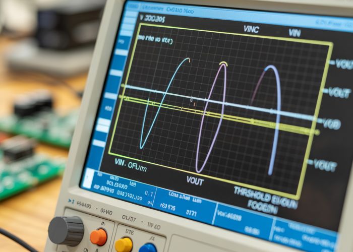
Tools like oscilloscopes or curve tracers can also be used to automatically generate VTCs, providing a more detailed and accurate representation. Specialized software can be also used to plot VTC based on measured values from the hardware setup.
Voltage Transfer Characteristic (VTC) FAQs
Here are some frequently asked questions about the voltage transfer characteristic (VTC) to help clarify its concepts.
What exactly does a Voltage Transfer Characteristic (VTC) tell us?
The voltage transfer characteristic (VTC) shows the output voltage of a circuit or device plotted against its input voltage. It’s a graphical representation of how the output responds to changes in the input. This allows us to understand the circuit’s behavior.
Why is the shape of the VTC important?
The shape reveals key aspects of the circuit’s functionality, such as gain, saturation regions, and threshold voltage. Different shapes signify different operating modes or behaviors. These shapes can also identify non-linearities.
What is the saturation region on a VTC?
The saturation region is the part of the voltage transfer characteristic where the output voltage stops changing significantly even with increasing input voltage. The circuit has reached its maximum output capability here. The operating mode of the circuit is fully on or fully off.
How can I use a VTC to find the switching threshold?
The switching threshold is the input voltage where the output voltage sharply transitions between its high and low states. On the voltage transfer characteristic, this is typically found at the point where the curve has the steepest slope. This point gives insight into when the device changes state.
So, there you have it! Hopefully, this simplified explanation makes understanding the voltage transfer characteristic a little less daunting. Now go forth and design some awesome circuits!