Understanding power system infrastructure fundamentally relies on a comprehensive substation components diagram. IEEE standards significantly influence the design and functionality of these critical nodes. The layout of a substation, detailed in the substation components diagram, dictates the flow and management of electrical power. Furthermore, various software tools aid engineers in visualizing and simulating the intricate substation components diagram, ensuring efficient and safe operations.
Substations are critical nodes within the electrical power grid. These facilities act as vital junctions.
At substations, voltage is transformed, power flow is managed, and system protection is implemented.
Understanding the intricacies of substation operation and the function of its various components is, therefore, paramount for anyone involved in the power industry.
This knowledge is especially crucial for engineers and technicians who design, maintain, and operate these complex systems.
The Substation’s Role in the Power Grid
A substation is a high-voltage facility that forms an integral part of an electrical generation, transmission, and distribution system. Its primary function is to transform voltage levels from high to low, or vice versa, to facilitate the efficient transmission and distribution of electrical power.
Substations perform several other critical functions, including:
-
Switching: Enabling connection or disconnection of transmission lines and other components.
-
Protection: Protecting the grid and substation equipment from faults and overloads.
-
Control: Monitoring and controlling the flow of power.
-
Voltage Regulation: Maintaining voltage levels within acceptable limits.
Without substations, long-distance power transmission would be infeasible due to voltage drop. Local distribution would be impossible because the voltage would be too high for safe use by homes and businesses.
Why Understanding Substation Components Matters
A thorough understanding of substation components is essential for several reasons:
-
Effective Operation and Maintenance: Knowing the function of each component allows for efficient troubleshooting, maintenance, and repair.
-
Safe Working Practices: Substations contain high-voltage equipment and understanding its potential hazards is crucial for ensuring the safety of personnel.
-
System Design and Upgrades: Engineers need to understand the capabilities and limitations of each component to design and upgrade substations effectively.
-
Reliable Power Delivery: A well-maintained and properly operated substation ensures a reliable supply of electrical power to consumers.
A Comprehensive Visual Guide
This article aims to provide a comprehensive visual guide to the key components found in a typical substation. Through detailed descriptions and illustrative diagrams, we will explore the function, operation, and importance of each component. This will help to develop a solid understanding of how substations work and their crucial role in the electrical power system. The focus is on clarity and ease of understanding, making this a valuable resource for both seasoned professionals and those new to the field.
Core Components: Power Flow and Transformation
Substations, at their essence, are about managing and directing electrical power. They accomplish this primarily through voltage transformation and power distribution. These vital functions are executed by core components, namely power transformers and busbars.
These elements work in tandem to receive power at one voltage level, convert it to another appropriate for transmission or distribution, and then efficiently distribute it throughout the substation and onwards to the grid.
Power Transformers: Voltage Transformation
Power transformers are arguably the most critical and expensive components within a substation. Their primary function is to step voltage up or down. This allows for efficient long-distance transmission at high voltages, and safe distribution to end-users at lower voltages.
At the generation end, transformers step up the voltage to minimize losses during transmission. At the distribution end, transformers step down the voltage to levels suitable for residential, commercial, and industrial consumption.
Types of Power Transformers
Different types of power transformers are used depending on the application and environmental conditions. The two most common types are oil-filled transformers and dry-type transformers.
Oil-filled transformers are typically used for high-voltage, high-power applications. They use oil as both a coolant and an insulator. The oil circulates through the transformer, dissipating heat and preventing electrical breakdown. Regular oil testing and maintenance are crucial for the reliable operation of these transformers.
Dry-type transformers are used in applications where oil-filled transformers are not suitable, such as indoors or in environmentally sensitive areas. They rely on air circulation and specialized insulation materials to dissipate heat. Dry-type transformers generally require less maintenance than oil-filled transformers, but they are typically limited to lower voltage and power ratings.
Internal Construction and Operation
A power transformer consists of two or more coils of wire, called windings, wrapped around a common iron core. The primary winding is connected to the incoming voltage, and the secondary winding is connected to the outgoing voltage.
The voltage transformation ratio is determined by the ratio of the number of turns in the primary winding to the number of turns in the secondary winding. When alternating current flows through the primary winding, it creates a changing magnetic field in the core. This changing magnetic field induces a voltage in the secondary winding.
The efficiency of a power transformer is typically very high, often exceeding 99%. However, losses do occur due to resistance in the windings, hysteresis in the core, and eddy currents.
Understanding the internal construction and operation of power transformers is crucial for diagnosing and troubleshooting potential problems.
Visual aids such as diagrams are invaluable in illustrating these concepts.
Busbars: Distributing Electrical Power
Busbars serve as the central nodes for distributing electrical power within the substation. They are essentially conductive bars, typically made of copper or aluminum, that act as common connection points for incoming and outgoing circuits.
Busbars facilitate the connection of various components, such as transformers, circuit breakers, and transmission lines, allowing for flexible and reliable power distribution.
Busbar Arrangements
The configuration of busbars within a substation significantly affects its reliability and operational flexibility. Several common busbar arrangements exist, each with its own advantages and disadvantages.
Single busbar arrangement: This is the simplest and most economical arrangement. All circuits are connected to a single busbar. However, a fault on the busbar will result in a complete shutdown of the substation.
Double busbar arrangement: This arrangement uses two busbars, allowing circuits to be switched between them. This provides increased reliability, as one busbar can be taken out of service for maintenance without interrupting power flow.
Ring busbar arrangement: In this arrangement, the busbars are arranged in a closed loop. This provides even greater reliability, as a fault on one section of the busbar will only interrupt power flow to a limited number of circuits.
Choosing the appropriate busbar arrangement depends on factors such as the size and importance of the substation, the required level of reliability, and the available budget.
Visual representations of these different busbar configurations are essential for understanding their operation and comparing their advantages and disadvantages.
Protection and Control Systems: Ensuring Reliability
Having explored the core components dedicated to power flow and transformation, the next crucial aspect of substation operation revolves around safeguarding the system. Substation reliability hinges on sophisticated protection and control systems that rapidly respond to abnormal conditions. These systems, comprised of interconnected devices, work in concert to isolate faults, prevent equipment damage, and maintain grid stability.
Circuit Breakers: The First Line of Defense Against Fault Currents
Circuit breakers are essential protection devices designed to interrupt fault currents. Fault currents are abnormally high currents that flow during short circuits or other electrical faults. Without circuit breakers, these currents could cause severe damage to equipment, potentially leading to widespread outages.
Circuit breakers act as switches that can automatically open and interrupt the flow of current when a fault is detected. This interruption isolates the faulted section of the system, preventing the fault from spreading and minimizing the impact on the overall power grid.
Types of Circuit Breakers
Different types of circuit breakers utilize various methods for interrupting the arc that forms when the contacts separate under fault conditions. Common types include:
-
Air-blast circuit breakers: Use a high-pressure air blast to extinguish the arc. These are typically used for high-voltage applications.
-
Oil circuit breakers: Use oil as an insulating and cooling medium to quench the arc. While still in use, they are gradually being replaced by more modern technologies.
-
SF6 circuit breakers: Utilize sulfur hexafluoride (SF6) gas as an insulating and arc-quenching medium. They are widely used in high-voltage substations due to their excellent performance and reliability.
-
Vacuum circuit breakers: Employ a vacuum chamber to interrupt the arc. These are commonly used in medium-voltage applications and are known for their compact size and low maintenance requirements.
(Include a diagram illustrating circuit breaker operation here, showcasing the key components and the arc-quenching mechanism.)
Protective Relays: The Brains Behind the Operation
Protective relays are intelligent devices that monitor electrical parameters within the substation, such as current, voltage, and frequency. Their primary role is to detect abnormal conditions, or faults, and initiate the tripping of circuit breakers to isolate the faulted section.
These relays are programmed with specific settings that define the acceptable operating ranges for these parameters. When a parameter deviates from its normal range, the relay detects the fault and sends a trip signal to the appropriate circuit breaker.
Types of Protective Relays
Numerous types of protective relays exist, each designed to detect specific types of faults or abnormal conditions. Some common types include:
-
Overcurrent relays: Detect excessive current flow, indicating a short circuit or overload.
-
Voltage relays: Detect abnormal voltage levels, such as undervoltage or overvoltage conditions.
-
Distance relays: Measure the impedance between the relay location and the fault location. They are used for protecting transmission lines.
-
Differential relays: Compare the current entering and leaving a protected zone. Any difference indicates a fault within that zone.
(Present a diagram of a typical protective relay scheme here, illustrating how the relay interacts with CTs, VTs, and circuit breakers.)
Current and Voltage Transformers (CTs & VTs/PTs): The Measurement Foundation for Protection
Current transformers (CTs) and voltage transformers (VTs), also known as potential transformers (PTs), play a crucial role in providing accurate measurements of current and voltage to protective relays and metering equipment. These instrument transformers isolate the high-voltage circuits from the low-voltage control circuits, ensuring the safety of personnel and equipment.
CTs step down the high currents flowing in the power system to lower, more manageable levels that can be safely measured by relays. Similarly, VTs step down high voltages to lower levels.
These transformers are connected in strategic locations within the substation to provide comprehensive monitoring of the system. The secondary windings of CTs and VTs are connected to protective relays, meters, and other monitoring devices, providing the necessary data for these devices to operate correctly.
(Illustrate how CTs and VTs are connected within the substation here, showing their placement relative to circuit breakers and other equipment.)
Surge Arresters: Shielding Against Transient Overvoltages
Surge arresters, also known as lightning arresters, are protective devices designed to protect substation equipment from transient overvoltages. These overvoltages can be caused by lightning strikes, switching operations, or other disturbances on the power system.
Surge arresters provide a low-impedance path to ground for these surges, diverting the excess energy away from sensitive equipment. This prevents damage to transformers, circuit breakers, and other critical components.
(Show a diagram illustrating surge arrester operation here, highlighting how it diverts the surge current to ground.)
Switching and Isolation: Maintenance and Operational Flexibility
Beyond the rapid response of protection systems, substations require mechanisms for controlled switching and isolation of equipment. This allows for safe maintenance, repairs, and operational flexibility. Isolators, also known as disconnect switches, are the key components that fulfill this crucial role. Unlike circuit breakers, isolators are not designed to interrupt fault currents. Instead, they provide a visible break in the circuit, ensuring the safety of personnel working on de-energized equipment.
Isolators (Disconnect Switches): Providing Visible Isolation
Isolators are manually or motor-operated switches that create an air gap in the electrical circuit. This physical separation provides a visual confirmation that the circuit is de-energized, enhancing safety during maintenance and repair activities.
The Core Function of Isolators
The primary function of an isolator is to provide visible isolation. This means that when the isolator is open, there is a clear and unambiguous physical gap in the electrical conductor. This gap assures personnel that the circuit is indeed de-energized, reducing the risk of electrical shock.
It is crucial to note that isolators should never be opened or closed while the circuit is carrying load current. Attempting to do so can result in a severe arc, potentially damaging the isolator and endangering personnel. Circuit breakers must first interrupt the load current before the isolator is operated.
Types of Isolators and Operating Mechanisms
Several types of isolators are available, each designed for specific voltage levels, current ratings, and operating conditions. Common types include:
-
Vertical Break Isolators: These isolators have contacts that move vertically to open or close the circuit. They are commonly used in outdoor substations due to their simple design and reliable operation.
-
Horizontal Break Isolators: In this design, the contacts move horizontally to create the isolating gap. They may be preferred in situations where vertical space is limited.
-
Center Break Isolators: These isolators feature a central contact that rotates to either connect or disconnect the circuit. They offer a compact design and are often used in confined spaces.
-
Pantograph Isolators: Employing a pantograph-like mechanism, these isolators are suitable for high-voltage applications and offer a large clearance distance.
The operating mechanisms for isolators can be manual, using a hand crank or lever, or motor-operated, allowing for remote control. Motor-operated isolators are often integrated into SCADA systems for enhanced operational flexibility.
Isolator Use in a Substation: A Visual Representation
[(Diagram of isolator use in a substation would be inserted here.)]
The diagram would visually depict isolators strategically placed within the substation to isolate various components, such as transformers, bus sections, and circuit breakers. Key elements to illustrate include:
-
Placement: Isolators positioned on either side of a circuit breaker to allow for breaker maintenance.
-
Visible Gap: A clear depiction of the air gap created when the isolator is open.
-
Interlocking: The use of interlocking mechanisms to prevent isolators from being opened under load.
By incorporating isolators into the substation design, operators gain the ability to safely isolate equipment, facilitating maintenance, repairs, and system upgrades while minimizing disruptions to power delivery.
Grounding and Safety: Ensuring Personnel and Equipment Protection
Having explored the critical role of switching and isolation in maintaining operational flexibility, we now turn to an equally vital aspect of substation design: grounding. A well-designed grounding system is not merely an afterthought; it’s the cornerstone of safety, protecting both personnel and equipment from the damaging effects of fault currents and voltage surges.
The Indispensable Role of a Robust Grounding System
The importance of a robust grounding system in a substation cannot be overstated. Its primary function is to provide a low-impedance path for fault currents to return to the source, ensuring the rapid operation of protective devices like circuit breakers and relays. Without an effective grounding system, fault currents can find unintended paths through equipment enclosures, structures, or even the ground itself, creating dangerous touch potentials and potentially causing severe electrical shock or equipment damage.
Furthermore, a properly designed grounding system helps to minimize the effects of transient overvoltages caused by lightning strikes or switching operations. These surges can damage sensitive electronic equipment and insulation, leading to equipment failure and service interruptions. A well-grounded system effectively dissipates these surges, protecting valuable assets and ensuring the reliability of the power supply.
Types of Grounding Systems: A Comparative Overview
Several types of grounding systems are commonly employed in substations, each with its own advantages and disadvantages depending on the specific application and operating conditions. The selection of the appropriate grounding system is a critical design decision that must consider factors such as fault current levels, soil resistivity, and the sensitivity of equipment to voltage disturbances.
-
Solid Grounding: In a solidly grounded system, the neutral point of the power transformer is directly connected to ground. This approach provides the lowest possible ground impedance, ensuring rapid fault clearing and minimizing voltage rise during ground faults. Solid grounding is commonly used in high-voltage systems where high fault currents are expected.
-
Resistance Grounding: Resistance grounding introduces a resistor between the neutral point and ground. This limits the magnitude of ground fault currents, reducing the risk of equipment damage and step and touch potentials. However, it may also slow down fault clearing times compared to solid grounding. Resistance grounding is often used in medium-voltage systems where it is desirable to limit fault current levels.
-
Reactance Grounding: Reactance grounding employs a reactor between the neutral point and ground. Similar to resistance grounding, this limits fault current levels, but it also introduces a reactive component that can affect system stability. Reactance grounding is less commonly used than solid or resistance grounding.
-
Ungrounded Systems: In an ungrounded system, there is no intentional connection between the neutral point and ground. While this can limit fault current during a single ground fault, it also allows the system voltage to rise to dangerous levels during sustained ground faults. Ungrounded systems are generally not recommended for substations due to the safety risks associated with overvoltages.
Key Components of a Typical Grounding System
A typical substation grounding system comprises several interconnected components designed to provide a comprehensive and reliable grounding network. These components work together to ensure the safety of personnel and equipment during normal and fault conditions.
-
Ground Grid: The ground grid is a network of buried conductors, typically copper or aluminum, that provides a low-impedance path to ground throughout the substation. The grid is designed to distribute fault currents evenly and minimize touch and step potentials.
-
Ground Rods: Ground rods are driven into the earth to provide a direct connection to the surrounding soil. They are typically made of copper or copper-clad steel and are strategically placed throughout the substation to enhance the grounding effectiveness.
-
Connections to Equipment: All metallic enclosures, structures, and equipment within the substation must be securely connected to the ground grid. This ensures that any fault current flowing through the equipment is safely directed to ground.
-
Ground Conductors: Ground conductors are used to connect various components of the grounding system together. They must be sized appropriately to handle the expected fault current levels.
-
Grounding Transformers: Grounding transformers are used to create a neutral point in systems that do not have one, allowing for the implementation of a grounded system. They are typically used in delta-connected systems.
By understanding the critical role of a robust grounding system, the different types of grounding methods, and the key components involved, engineers and technicians can ensure the safety and reliability of substation operations. A well-designed and maintained grounding system is an essential investment in protecting personnel and equipment from the hazards of electrical faults.
Having equipped our substations with robust grounding systems to safeguard against faults and overvoltages, the next critical layer of functionality concerns the intelligent operation and oversight of the entire facility. This is where control and monitoring systems come into play, enabling remote operation, real-time data acquisition, and enhanced overall reliability.
Control and Monitoring: Remote Operation and Data Acquisition
Modern substations are no longer isolated entities; they are integral nodes within a vast, interconnected power grid. Effective control and monitoring systems are essential for maintaining grid stability, optimizing performance, and responding swiftly to changing conditions. These systems rely heavily on two key components: the control building and the Supervisory Control and Data Acquisition (SCADA) system.
The Control Building: Central Nervous System of the Substation
The control building serves as the central hub for all control, protection, and communication equipment within the substation. It’s more than just a physical structure; it’s the brain of the substation, housing the sophisticated electronics that enable operators to monitor and manage the entire facility remotely.
Purpose and Functionality
The primary purpose of the control building is to provide a secure and environmentally controlled space for sensitive electronic equipment. This ensures reliable operation of critical systems, protecting them from the elements, unauthorized access, and electromagnetic interference.
Inside, you’ll typically find a range of equipment, including:
- Protective relays: Detect faults and initiate tripping of circuit breakers.
- Control panels: Allow operators to manually control substation equipment.
- Communication equipment: Enables remote monitoring and control via SCADA.
- Metering equipment: Measures voltage, current, and power flow.
- Batteries and chargers: Provide backup power in case of a power outage.
- SCADA Remote Terminal Units (RTUs): Interface with field devices and transmit data to the central SCADA system.
Environmental Considerations
Maintaining a stable environment within the control building is paramount. Temperature and humidity must be carefully controlled to prevent equipment malfunction and ensure long-term reliability. Air conditioning systems, heating systems, and humidity control devices are often employed to achieve this.
Furthermore, fire suppression systems are critical to protect the sensitive electronic equipment in case of a fire. These systems typically use clean agents that won’t damage the equipment or pose a risk to personnel.
SCADA: Eyes and Ears of the Grid
Supervisory Control and Data Acquisition (SCADA) systems are the eyes and ears of the substation, enabling remote monitoring and control of equipment and processes. SCADA systems collect data from various points within the substation, transmit it to a central control center, and allow operators to issue commands to control equipment remotely.
Remote Monitoring and Control Capabilities
SCADA systems provide operators with a real-time view of the substation’s operating conditions, including voltage levels, current flows, equipment status, and alarm conditions.
This allows operators to:
- Monitor equipment performance and identify potential problems early.
- Control circuit breakers, switches, and other equipment remotely.
- Adjust voltage levels to optimize power flow.
- Respond quickly to fault conditions and restore power.
- Analyze historical data to identify trends and improve performance.
Enhancing Operation and Reliability
The benefits of SCADA systems in improving substation operation and reliability are numerous. By providing real-time data and remote control capabilities, SCADA systems enable operators to respond quickly to changing conditions, optimize power flow, and prevent outages.
Moreover, SCADA systems can automate many routine tasks, freeing up operators to focus on more critical issues. This can improve efficiency, reduce operating costs, and enhance overall grid reliability. The ability to proactively manage the grid based on real-time data is invaluable.
Having equipped our substations with robust grounding systems to safeguard against faults and overvoltages, the next critical layer of functionality concerns the intelligent operation and oversight of the entire facility. This is where control and monitoring systems come into play, enabling remote operation, real-time data acquisition, and enhanced overall reliability.
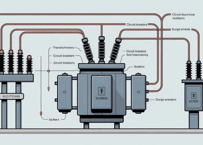
Visual Summary: Comprehensive Substation Components Diagram
To consolidate the information presented throughout this guide, we now offer a detailed visual representation of a typical substation, incorporating all key components discussed. This diagram serves as a valuable reference tool for engineers, technicians, and anyone seeking a clear understanding of substation architecture.
Deconstructing the Diagram: A Component-by-Component Breakdown
The comprehensive substation diagram showcases the interconnectedness of various components, emphasizing their spatial relationships and functional roles. Let’s dissect the key elements:
-
Power Transformer: This is the workhorse, responsible for stepping voltage up or down to facilitate efficient transmission and distribution. Its location is critical, often near the high-voltage side of the substation.
-
Busbars: These act as the central distribution points, channeling electrical power to various outgoing feeders. Different busbar arrangements offer varying levels of redundancy and operational flexibility.
-
Circuit Breakers: Positioned strategically throughout the substation, circuit breakers are the primary protection devices, interrupting fault currents to prevent damage to equipment and maintain system stability.
-
Protective Relays: These intelligent devices continuously monitor current and voltage levels, detecting abnormal conditions and initiating circuit breaker tripping when necessary. Their settings are meticulously calibrated to ensure optimal protection.
-
Current and Voltage Transformers (CTs & VTs/PTs): These instruments provide scaled-down replicas of system currents and voltages to protective relays and metering equipment, enabling accurate monitoring and control.
-
Surge Arresters: These safeguard equipment from transient overvoltages caused by lightning strikes or switching operations, diverting excess energy to ground.
-
Isolators (Disconnect Switches): Primarily used for isolating equipment for maintenance purposes, isolators provide a visible break in the circuit, ensuring personnel safety. Note: They are not designed to interrupt load current.
-
Grounding System: This essential safety feature provides a low-impedance path for fault currents, protecting personnel and equipment from dangerous voltage rises.
-
Control Building: Housing the substation’s control, protection, and communication equipment, the control building serves as the central nervous system of the facility.
-
SCADA System: Enabling remote monitoring and control, the SCADA system provides operators with real-time data and the ability to adjust substation parameters from a central location.
Using the Diagram as a Reference Tool
This comprehensive diagram is designed to be a quick and easy reference for identifying and understanding the function of various substation components. By visually associating each component with its role within the overall system, users can gain a deeper appreciation for the complexity and sophistication of modern substations.
It is useful as a training aid for new technicians, a refresher for experienced engineers, and a valuable resource for anyone seeking to expand their knowledge of power system infrastructure.
Frequently Asked Questions About Substation Components Diagrams
Here are some common questions related to understanding substation components diagrams. We hope these FAQs clarify any confusion and help you better interpret these essential schematics.
What is the purpose of a substation components diagram?
A substation components diagram provides a visual representation of all the equipment and their connections within an electrical substation. This diagram aids in understanding the overall functionality of the substation and is crucial for maintenance, troubleshooting, and expansion planning. Analyzing a substation components diagram allows engineers and technicians to quickly grasp the system’s architecture.
What are the key components typically shown in a substation components diagram?
Common components illustrated in a substation components diagram include transformers, circuit breakers, disconnect switches, busbars, surge arresters, and control systems. These diagrams also depict the connections between these components, showing how power flows through the substation. The diagram indicates the ratings and specifications of each device.
Why is it important to understand the symbols used in a substation components diagram?
Understanding the symbols used in a substation components diagram is vital for accurate interpretation. Standardized symbols represent each component, allowing viewers to quickly identify and understand the function of each element within the substation. Incorrect interpretation of symbols can lead to errors in maintenance or operation.
Where can I find examples of a substation components diagram?
Examples of a substation components diagram can be found in engineering textbooks, technical manuals related to electrical substations, and online resources provided by electrical equipment manufacturers and professional organizations. Many websites offer detailed examples to help you learn how to read and interpret these diagrams effectively.
So there you have it! Hopefully, this guide has shed some light on the substation components diagram. Now go forth and put that knowledge to good use!