Understanding your water system is crucial for home maintenance, and the pressure tank serves as its heart, regulating water flow and pressure. A pressure tank diagram is essential for deciphering its workings. Well pumps are integral to this system, responsible for drawing water from your water source into the tank. Identifying the components within a pressure tank diagram, such as the bladder and air valve, enables you to troubleshoot common issues. Proper maintenance of your entire system, including understanding the pressure tank diagram, will ensure longevity and optimal water pressure for your home.
Decoding Pressure Tank Diagrams: A Comprehensive Layout Guide
Understanding a pressure tank diagram is crucial for troubleshooting, maintenance, and even initial installation. This guide outlines the optimal article layout to help readers quickly and effectively decode their diagrams.
Introduction: Why Pressure Tank Diagrams Matter
Begin with a concise explanation of why pressure tank diagrams are important. Highlight their role in:
- Identifying components and their relationships.
- Facilitating accurate troubleshooting of common issues like water hammer or short cycling.
- Aiding in proper maintenance and repair procedures.
- Supporting correct installation of the pressure tank.
Emphasize that even a basic understanding can save time, money, and prevent potential damage to the water system.
Section 1: Essential Components Depicted in a Pressure Tank Diagram
This section forms the core of understanding any "pressure tank diagram". Use visuals liberally here.
Identifying Common Pressure Tank Parts
Provide a labelled diagram (or multiple diagrams showcasing variations) illustrating typical pressure tank components. Each component should be clearly numbered or lettered and correspond to a descriptive list.
-
List of Components:
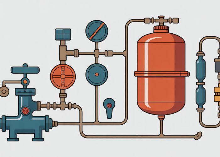
- Tank Shell: The outer casing of the pressure tank.
- Water Inlet/Outlet: The connection point for water entering and exiting the tank.
- Air Inlet (Schrader Valve): Used to adjust the air pressure within the tank.
- Bladder (or Diaphragm): The flexible membrane separating water and air (in bladder/diaphragm tanks).
- Air Charge (Air Cushion): The compressed air providing pressure.
- Pressure Switch: Detects water pressure and controls the well pump.
- Pressure Gauge: Indicates the water pressure within the tank.
- Drain Valve: Used to drain the tank for maintenance or repairs.
- Tank Tee: Connects the tank, pump, and plumbing.
- Check Valve: Prevents backflow of water into the well.
Types of Pressure Tanks and Diagram Variations
Explain the difference between different types of pressure tanks (e.g., bladder, diaphragm, air-over-water). Illustrate how diagrams may differ depending on the tank type.
- Bladder Tank Diagram: Focus on the bladder separating water and air.
- Diaphragm Tank Diagram: Show a diaphragm creating the separation.
- Air-Over-Water Tank Diagram: Explain the absence of a physical barrier and the importance of air maintenance.
Use comparative visuals to clearly showcase these differences.
Section 2: Understanding Diagram Symbols and Conventions
This section addresses the language of "pressure tank diagrams."
Common Symbols Used in Pressure Tank Diagrams
Create a table clearly defining common symbols used in the diagrams.
| Symbol | Component | Description |
|---|---|---|
| Pressure Switch | A schematic representation of a pressure switch. | |
| Check Valve | Symbol indicating a one-way valve. | |
| Pressure Gauge | A circular symbol representing a gauge. | |
| Pipe/Plumbing Lines | Lines representing pipes connecting components. | |
| Drain Valve | A valve symbol for draining water. | |
| Pump | A symbol representing a water pump. |
Reading and Interpreting Flow Direction
Explain how flow direction is indicated on the diagram, typically using arrows. Explain how to follow the flow of water through the system based on the diagram.
Section 3: Troubleshooting Using a Pressure Tank Diagram
Demonstrate the practical application of understanding the diagram.
Identifying Potential Issues Based on the Diagram
Provide scenarios where the diagram aids in identifying problems.
- Scenario 1: Short Cycling: A diagram can help trace the path from the pressure switch to the pump, helping to identify potential causes of rapid on/off cycling.
- Scenario 2: Low Water Pressure: The diagram can guide the user to check for blockages in the inlet/outlet or issues with the pressure switch.
- Scenario 3: Water Hammer: Understanding the tank’s position in the system via the diagram can point to potential solutions for water hammer (e.g., adding or adjusting air pressure).
Step-by-Step Troubleshooting Guide with Diagram References
Create a numbered list guiding the reader through a basic troubleshooting process, referencing specific components on the diagram at each step.
- Identify the Symptom: (e.g., Low water pressure)
- Consult the Diagram: Locate the pressure tank, pressure switch, and water inlet/outlet on the diagram.
- Check for Obstructions: Using the diagram as a guide, physically inspect the inlet/outlet for any blockages.
- Test the Pressure Switch: Locate the pressure switch on the diagram and test its functionality (if appropriate and safe to do so).
- Adjust Air Pressure (If Applicable): Locate the air inlet (Schrader valve) on the diagram and adjust the air pressure according to the manufacturer’s specifications.
Section 4: Maintenance and Diagram Use
Highlight how diagrams are useful for routine maintenance.
Using the Diagram for Maintenance Procedures
Explain how the diagram helps in planning and executing maintenance tasks.
- Draining the Tank: The diagram shows the location of the drain valve for easy access.
- Checking Air Pressure: The diagram highlights the air inlet (Schrader valve).
- Replacing Components: The diagram provides a visual guide for disconnecting and replacing parts like the pressure switch or check valve.
Safety Precautions When Working with Pressure Tanks
Emphasize safety measures when working with pressure tanks, especially concerning electrical components and pressurized systems. This section should be strongly worded and might include:
- Always disconnect power before working on any electrical components.
- Relieve pressure in the tank before disconnecting any plumbing.
- Consult a qualified professional if you are unsure about any procedure.
Decoding Your Pressure Tank Diagram: FAQs
Have questions after reading our pressure tank diagram guide? Here are some common inquiries and quick answers to help you understand your system better.
What does the arrow direction on a pressure tank diagram indicate?
The arrows in a pressure tank diagram usually show the direction of water flow. Pay close attention to where the arrows originate and terminate; this indicates the flow path from the water source, through the tank, and to your plumbing.
Where can I typically find the pressure tank diagram on my tank?
While not always the case, some manufacturers will attach a simplified pressure tank diagram directly to the tank itself. Check for a label or sticker, often near the pressure switch or other components. If not there, consult the manufacturer’s website or your tank’s manual.
What if my pressure tank diagram doesn’t match my actual setup?
Differences can occur due to variations in plumbing configurations or modifications over time. The pressure tank diagram is just a general guide. If discrepancies exist, focus on understanding the function of each component and how they’re interconnected in your system. Consulting a plumber is recommended if you’re unsure.
Why is understanding the pressure tank diagram important for troubleshooting?
A pressure tank diagram helps you identify the various components and their relationships within the system. This understanding is crucial for troubleshooting problems, such as leaks or pressure fluctuations, by allowing you to pinpoint the potential source of the issue and how to address it.
So there you have it! Hopefully, this guide helped you decode your pressure tank diagram. Now you can confidently tackle some basic troubleshooting. Happy plumbing!