Understanding the diode positive side is crucial for anyone working with electronics. A PN junction, a fundamental concept in semiconductor physics, dictates the behavior of current flow through a diode. Texas Instruments manufactures various diodes, ensuring that proper identification of the diode positive side is achievable using component datasheets. Multimeters, essential tools in any electronics lab, allow for easy determination of the diode positive side through resistance measurements. Correctly identifying the diode positive side is vital for ensuring circuit functionality within electronic devices.
Diode Positive Side: The Definitive Guide You Need!
Understanding the "diode positive side" is crucial for anyone working with electronics. This guide provides a detailed breakdown of everything you need to know, from identifying it to understanding its function within a circuit.
Identifying the Diode Positive Side (Anode)
The positive side of a diode, also known as the anode, is often marked visually on the diode body itself. However, markings vary, so knowing how to identify it is vital.
Visual Indicators
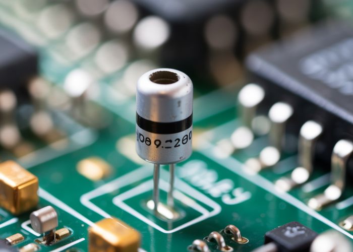
- Band/Stripe: The most common indicator is a band or stripe, usually silver or gray, located at one end of the diode. This band represents the cathode (negative side), not the anode. Therefore, the opposite end is the anode.
- Diode Symbol: On circuit diagrams and printed circuit boards (PCBs), the diode is represented by a triangle pointing towards a line. The triangle points towards the cathode, and the base of the triangle represents the anode.
- Color Coding (Less Common): While less frequent in modern diodes, older components might use color bands to indicate the diode’s properties. The direction of the color bands, if present, might indirectly hint at the polarity. Consult the diode’s datasheet for specific color code meanings.
Using a Multimeter
If visual indicators are absent or unclear, a multimeter offers a reliable method for determining polarity.
- Diode Mode: Set your multimeter to "Diode Test" mode. This mode sends a small voltage through the diode.
- Connect Probes: Connect the red (positive) multimeter probe to one end of the diode, and the black (negative) probe to the other end.
- Observe Reading:
- Forward Bias (Conducting): If the multimeter displays a voltage drop (typically between 0.3V and 0.7V for silicon diodes), the red probe is connected to the anode, and the black probe is connected to the cathode. This is because the diode is forward biased and allowing current to flow.
- Reverse Bias (Non-Conducting): If the multimeter displays "OL" (Overload) or a very high resistance value, the diode is reverse biased and not conducting. The red probe is connected to the cathode, and the black probe is connected to the anode.
- Reverse Connections: Swap the multimeter probes and repeat the test. You should observe the opposite result compared to the first test.
Function of the Anode in Circuit Operation
The anode’s primary function is to allow current to flow through the diode when it is positively biased. This is the fundamental principle behind diode operation.
Forward Bias
- Voltage Requirement: When the voltage at the anode is higher than the voltage at the cathode by at least the diode’s forward voltage (also known as the "turn-on voltage" or "threshold voltage"), the diode is forward biased.
- Current Flow: In forward bias, the diode acts like a closed switch, allowing current to flow from the anode to the cathode.
- Voltage Drop: A small voltage drop occurs across the diode in forward bias. This voltage drop is characteristic of the diode material (e.g., ~0.7V for silicon diodes, ~0.3V for germanium diodes).
Reverse Bias
- Voltage Requirement: When the voltage at the anode is lower than the voltage at the cathode, the diode is reverse biased.
- Current Blockage: In reverse bias, the diode acts like an open switch, blocking current flow.
- Reverse Leakage Current: A very small amount of current, called reverse leakage current, still flows through the diode in reverse bias. This current is usually negligible but increases with temperature.
- Breakdown Voltage: If the reverse voltage exceeds the diode’s breakdown voltage, the diode will conduct in the reverse direction, potentially damaging the device.
Understanding Diode Datasheets
Datasheets provide critical information about a diode’s electrical characteristics, including the anode and cathode specifications.
Key Parameters Relating to the Anode
- Forward Voltage (Vf): The voltage drop across the diode when it is forward biased and conducting a specific current. This voltage is measured from the anode to the cathode.
- Maximum Forward Current (If): The maximum amount of current the diode can handle continuously in the forward direction without being damaged. This current flows from the anode to the cathode.
- Reverse Breakdown Voltage (Vr): The maximum reverse voltage that can be applied to the diode before it breaks down and conducts in the reverse direction. The voltage is specified with the anode being negative relative to the cathode.
- Reverse Leakage Current (Ir): The small amount of current that flows through the diode when it is reverse biased. This current is measured from the cathode to the anode.
FAQs About Diode Positive Side (Anode)
Here are some frequently asked questions to help further clarify the concepts discussed in our guide about the diode positive side.
What’s the official name for the diode positive side?
The diode positive side is officially called the anode. Knowing this terminology is crucial for understanding diode datasheets and circuit diagrams.
How can I identify the diode positive side (anode) on a physical diode?
Typically, the diode positive side (anode) is identified by the longer lead, or by the band located at the other end which marks the cathode (negative side). Double-check the datasheet for your specific diode model, as markings can vary.
Why is the diode positive side important for circuit design?
The diode positive side dictates the direction of current flow. Diodes allow current to flow easily from the anode to the cathode but block it in the reverse direction. Therefore, correct orientation is critical for circuit functionality.
What happens if I connect a diode backwards?
Connecting a diode backward in a circuit designed for forward current flow will typically block the current. In some cases, applying excessive reverse voltage can damage or destroy the diode. Always ensure correct polarity by identifying the diode positive side before installation.
Alright, hopefully, this guide helped clear up any confusion about the diode positive side! Now go build something awesome, and remember to double-check your polarity! Happy experimenting!