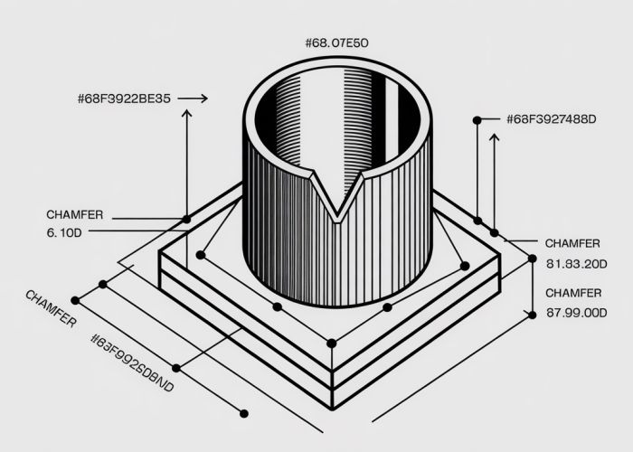
Understanding the significance of precision in manufacturing, particularly when dimensioning a chamfer, is crucial for engineers and designers alike. The American Society of Mechanical Engineers (ASME) provides standards that greatly assist with this process. Furthermore, the practical application of Computer-Aided Design (CAD) software facilitates accurate dimensioning, enabling consistency in production. Skilled machinists utilize these dimensions for precise execution, ensuring parts meet specified tolerances. Properly dimensioning a chamfer guarantees that components fit together correctly and function as intended.

Mastering Chamfer Dimensioning: A Comprehensive Guide
Chamfers are beveled edges added to parts for various reasons, including deburring, easing assembly, and improving aesthetics. Accurately defining a chamfer’s size and location – dimensioning a chamfer – is crucial for manufacturing and quality control. This guide will provide a structured approach to understanding and correctly applying chamfer dimensioning techniques.
Understanding the Basics of Chamfers
What is a Chamfer?
A chamfer is a sloped or angled edge formed between two surfaces. It is commonly a 45-degree angle but can be of any specified angle. Think of it as a small, flattened corner.
Why Use Chamfers?
Chamfers are useful in several situations:
- Deburring: Removing sharp edges to prevent injuries or damage during handling.
- Ease of Assembly: Guiding mating parts together more smoothly, preventing binding or interference.
- Aesthetics: Improving the appearance of a part by creating a more refined edge.
- Stress Relief: Reducing stress concentrations at sharp corners, potentially increasing the lifespan of a part.
Methods for Dimensioning a Chamfer
There are several accepted methods for dimensioning a chamfer, each with its own advantages depending on the application. Selecting the appropriate method is key to avoiding ambiguity and ensuring proper manufacturing.
Method 1: Angle and Distance
This is the most common and widely understood method. It involves specifying the angle of the chamfer and the distance along one of the surfaces forming the chamfer.
-
45-Degree Chamfers: For 45-degree chamfers, the dimension is typically expressed as "distance x 45°". For example, "1.0 x 45°" indicates a chamfer with a 1.0 unit distance along one surface at a 45-degree angle. This is the most simple and widely understood method.
-
Non-45-Degree Chamfers: For chamfers with angles other than 45 degrees, both the distance and the angle must be explicitly stated. For example, "1.5 x 30°" signifies a chamfer with a 1.5 unit distance and a 30-degree angle.
Method 2: Two Distances
This method specifies the distances along both surfaces that form the chamfer. It’s suitable when the exact angle is not critical, but the overall size of the chamfer is important.
- Specifying Distances: Both distances must be clearly labeled on the drawing. This method is less common than the angle and distance method but can be useful in specific situations.
Method 3: Direct Length
This method specifies the direct length (hypotenuse) of the chamfer and an angle.
- Example: A chamfer might be dimensioned as "Length = 2.0, Angle = 45°". While functional, this is less common due to the added calculation step for the machinist.
Best Practices for Chamfer Dimensioning
To ensure clear and unambiguous communication, follow these best practices when dimensioning chamfers:
- Clarity is Key: Always choose the dimensioning method that is easiest to understand and interpret for the intended audience (e.g., machinists, inspectors).
- Consistency: Use the same dimensioning method throughout a single drawing or project.
- Accuracy: Specify the required tolerances for both the angle and the distance(s) to ensure the chamfer meets the design requirements.
- Use Leaders and Arrows: Use leader lines and arrows to clearly indicate the surfaces to which the dimensions apply.
- Avoid Over-Dimensioning: Do not provide redundant dimensions that could lead to conflicting interpretations. One method is preferred over multiple methods of dimensioning the same chamfer.
- Consider Manufacturing Processes: Select a dimensioning method that is compatible with the manufacturing processes that will be used to create the chamfer.
Example Chamfer Dimensioning Scenarios
Let’s consider some practical examples.
| Scenario | Dimensioning Method | Dimension | Explanation |
|---|---|---|---|
| 45-degree deburring on a shaft | Angle and Distance | 0.5 x 45° | A small chamfer (0.5 units) at 45 degrees is used to remove the sharp edge. |
| Angled Chamfer on a block | Angle and Distance | 2.0 x 60° | A chamfer with a distance of 2.0 units and an angle of 60 degrees. |
| Specific width/height | Two Distances | Distance A = 1.0, Distance B= 1.5 | The distances of each leg of the right triangle are dimensioned independently. |
By adhering to these principles and practices, you can effectively dimension chamfers and ensure that your designs are accurately manufactured.
Chamfer Dimensioning FAQs: Secrets Revealed
This FAQ section addresses common questions about chamfer dimensioning, clarifying key concepts and techniques discussed in our main article.
What’s the most common way to dimension a chamfer?
The most common method involves specifying the distance along one face and the angle of the chamfer. This method directly communicates the physical dimensions of the chamfer.
Can I dimension a chamfer using two distances?
Yes, you can. This is especially useful when the chamfer angle isn’t critical or is difficult to measure. This method requires specifying the setback distance on both adjacent faces to define the chamfer.
What if the chamfer is 45 degrees?
For 45-degree chamfers, you can often simplify the dimensioning by stating "CHAM 45° x [distance]". This implies the chamfer is symmetrical, with the same setback distance on both faces. This is the quickest way to communicate the dimensioning of a chamfer
What should I do if the chamfer is non-standard angle?
For non-standard chamfer angles, dimensioning a chamfer requires indicating both the angle and one linear dimension (usually the setback distance). Clearly labeling the angle is critical for accurate manufacturing.
So, there you have it! Hopefully, you’re now feeling more confident about dimensioning a chamfer. Go on and give it a try – you might surprise yourself!