Understanding circuit board types is fundamental to anyone involved in electronics manufacturing. The IPC, a leading organization, establishes critical standards for these boards, impacting everything from design to assembly. A key attribute of different circuit board types is their layer count, directly influencing their complexity and application. The design phase often utilizes EDA tools to optimize layout for various circuit board types. Moreover, designers like Grace Hopper, though pre-dating modern PCB manufacturing, embodied the problem-solving ethos that guides the creation of innovative and efficient circuit board types.
Look around you. From the smartphone in your hand to the sophisticated control systems in your car, modern life is inextricably linked to electronics. At the heart of nearly every electronic device lies a component so fundamental, yet often unseen: the circuit board.
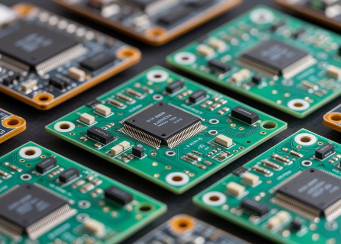
These unassuming green (or sometimes other colors) panels are the unsung heroes of our digital age, the very foundation upon which our increasingly interconnected world is built. They are the silent enablers, orchestrating the flow of electricity that brings our devices to life.
This article aims to peel back the layers of mystery surrounding circuit boards, providing a comprehensive guide to the diverse types that exist. We’ll explore their unique characteristics, applications, and the critical role they play in shaping the functionality and performance of electronic devices.
Whether you’re an experienced engineer, a passionate hobbyist, or simply curious about the inner workings of electronics, understanding the nuances of different circuit board types is invaluable.
The Ubiquitous Circuit Board: A Foundation of Modern Electronics
Circuit boards, more formally known as Printed Circuit Boards (PCBs), serve as the central nervous system for electronic devices. They provide a structured and organized platform for mounting and connecting electronic components.
Think of them as miniature cities, with carefully planned routes (traces) that guide the flow of electricity between buildings (components). Without these meticulously designed pathways, electronic devices would be chaotic and non-functional.
PCBs transform a jumble of discrete parts into a cohesive, working system. Their importance cannot be overstated.
A Comprehensive Guide: Navigating the PCB Landscape
The world of circuit boards is surprisingly diverse. Different applications demand different characteristics, leading to a wide array of PCB types, each with its own strengths and weaknesses.
This guide is designed to provide a clear and concise overview of these variations, empowering you to make informed decisions when selecting the right PCB for a specific project or application. We’ll delve into the key features that differentiate these boards.
We will examine:
- Layer count
- Flexibility
- Manufacturing techniques.
Why Understanding PCB Types Matters
The value of understanding different PCB types extends far beyond mere curiosity. For engineers, selecting the appropriate PCB is critical for ensuring the reliability, performance, and cost-effectiveness of their designs.
Hobbyists can benefit from this knowledge by optimizing their projects, troubleshooting issues more effectively, and expanding their creative possibilities.
Even those with a general interest in electronics will gain a deeper appreciation for the complexity and ingenuity behind the devices they use every day.
By understanding the subtle differences between PCB types, one can unlock a greater understanding of electronics as a whole. This knowledge will empower you to innovate, troubleshoot, and appreciate the intricate world within our devices.
Look around you. From the smartphone in your hand to the sophisticated control systems in your car, modern life is inextricably linked to electronics. At the heart of nearly every electronic device lies a component so fundamental, yet often unseen: the circuit board.
These unassuming green (or sometimes other colors) panels are the unsung heroes of our digital age, the very foundation upon which our increasingly interconnected world is built. They are the silent enablers, orchestrating the flow of electricity that brings our devices to life.
This article aims to peel back the layers of mystery surrounding circuit boards, providing a comprehensive guide to the diverse types that exist. We’ll explore their unique characteristics, applications, and the critical role they play in shaping the functionality and performance of electronic devices.
Whether you’re an experienced engineer, a passionate hobbyist, or simply curious about the inner workings of electronics, understanding the nuances of different circuit board types is invaluable.
The Ubiquitous Circuit Board: A Foundation of Modern Electronics
Circuit boards, more formally known as Printed Circuit Boards (PCBs), serve as the central nervous system for electronic devices. They provide a structured and organized platform for mounting and connecting electronic components.
Think of them as miniature cities, with carefully planned routes (traces) that guide the flow of electricity between buildings (components). Without these meticulously designed pathways, electronic devices would be chaotic and non-functional.
PCBs transform a jumble of discrete parts into a cohesive, working system. Their importance cannot be overstated.
From the simplest LED circuits to complex computer motherboards, the design and construction of PCBs directly influence the capabilities of the final product. One of the most fundamental ways to categorize these essential components is by the number of layers they possess, which dictates their complexity and application range. Let’s dissect the core PCB types based on their layer count, revealing the unique characteristics of single-sided, double-sided, and multilayer boards.
Layer by Layer: Exploring Core PCB Types Based on Layers
The layer count in a PCB is a primary determinant of its capabilities. It directly impacts the complexity of the circuits that can be implemented, the density of components, and the overall performance of the electronic device. PCBs are broadly classified into three main types based on their layer count: single-sided, double-sided, and multilayer. Each type caters to specific needs, offering a trade-off between simplicity, cost, and functionality.
Single-Sided Boards: Simplicity and Limitations
Single-sided PCBs, as the name suggests, feature a single layer of conductive material, typically copper, on one side of the board. Electronic components are mounted on the opposite side, with leads passing through holes to be soldered to the copper traces.
Characteristics and Applications
These boards are the simplest and most cost-effective type of PCB. They are typically used in low-density, simple electronic devices where complex circuitry is not required. Typical applications include:
- Simple LED lighting circuits.
- Basic power supplies.
- Calculator circuits.
- Simple sensor boards.
Advantages and Disadvantages
The advantages of single-sided PCBs include:
- Low manufacturing cost.
- Simple design and production process.
- Suitable for beginners and hobbyists.
However, they also have significant disadvantages:
- Limited circuit complexity.
- Low component density.
- Susceptible to electromagnetic interference (EMI).
- Only suitable for the least complex electronic applications.
Double-Sided Boards: Expanding Possibilities
Double-sided PCBs have a layer of conductive material on both sides of the board. This allows for more complex circuits and a higher component density compared to single-sided boards.
Characteristics and Component Mounting
Double-sided boards enable more intricate circuit designs. They allow for components to be mounted on both sides of the board, significantly increasing the available space and routing possibilities.
Components are connected using two primary methods:
- Through-hole technology: Component leads pass through holes drilled in the board and are soldered on the opposite side.
- Surface Mount Technology (SMT): Components are soldered directly onto the surface of the board without the need for drilled holes.
Complexity and Functionality Compared
Compared to single-sided boards, double-sided PCBs offer:
- Increased circuit complexity.
- Higher component density.
- Improved signal routing flexibility.
These enhancements make them suitable for a wider range of applications, including:
- More advanced power supplies.
- Audio amplifiers.
- Industrial control circuits.
- Some computer peripherals.
Multilayer Boards: The Apex of Complexity
Multilayer PCBs consist of three or more layers of conductive material, which are laminated together with insulating layers in between. These layers are interconnected using vias, which are small holes that are plated with conductive material to create electrical connections between layers.
Layered Construction and Interconnection
The construction of multilayer boards is significantly more complex than single or double-sided boards. The layers are precisely aligned and bonded together under high temperature and pressure.
Vias are essential for connecting different layers. There are several types of vias:
- Through-hole vias: Pass through all layers of the board.
- Blind vias: Connect an outer layer to one or more inner layers.
- Buried vias: Connect two or more inner layers without reaching the outer layers.
Benefits of Increased Density and Complexity
Multilayer PCBs offer several significant advantages:
- High component density: Allows for more components to be packed into a smaller area.
- Increased circuit complexity: Enables the implementation of complex digital and analog circuits.
- Improved signal integrity: Reduces noise and interference, leading to better performance.
- Enhanced power distribution: Provides more efficient and stable power delivery to components.
Applications in Advanced Electronics
Multilayer PCBs are essential in modern, complex electronic devices, including:
- Computer motherboards: Facilitating the high-speed communication between processors, memory, and other components.
- Smartphones: Enabling the integration of numerous functions into a compact form factor.
- Aerospace and military equipment: Providing reliable performance in harsh environments.
- Medical devices: Ensuring the accuracy and reliability of critical life-saving equipment.
The choice of PCB type based on layer count is a critical design decision. It balances cost, complexity, and performance requirements. As electronics continue to evolve, understanding these fundamental differences is essential for engineers and designers to create innovative and effective solutions.
Look around you. From the smartphone in your hand to the sophisticated control systems in your car, modern life is inextricably linked to electronics. At the heart of nearly every electronic device lies a component so fundamental, yet often unseen: the circuit board.
These unassuming green (or sometimes other colors) panels are the unsung heroes of our digital age, the very foundation upon which our increasingly interconnected world is built. They are the silent enablers, orchestrating the flow of electricity that brings our devices to life.
This article aims to peel back the layers of mystery surrounding circuit boards, providing a comprehensive guide to the diverse types that exist. We’ll explore their unique characteristics, applications, and the critical role they play in shaping the functionality and performance of electronic devices.
Whether you’re an experienced engineer, a passionate hobbyist, or simply curious about the inner workings of electronics, understanding the nuances of different circuit board types is invaluable.
The Ubiquitous Circuit Board: A Foundation of Modern Electronics
Circuit boards, more formally known as Printed Circuit Boards (PCBs), serve as the central nervous system for electronic devices. They provide a structured and organized platform for mounting and connecting electronic components.
Think of them as miniature cities, with carefully planned routes (traces) that guide the flow of electricity between buildings (components). Without these meticulously designed pathways, electronic devices would be chaotic and non-functional.
PCBs transform a jumble of discrete parts into a cohesive, working system. Their importance cannot be overstated.
From the simplest single-layer boards to the most complex multi-layered designs, we have examined how the number of layers dictates a circuit board’s capabilities. But the story doesn’t end there. Another critical characteristic that defines the functionality and applicability of a PCB is its flexibility. The capacity to bend, twist, or maintain a rigid structure opens up a new dimension in electronic design, allowing for innovative solutions tailored to specific constraints and requirements.
Bend or Break: Examining PCB Types Based on Flexibility
The world of circuit boards extends beyond the number of layers they possess. Just as crucial to consider is their physical flexibility, or lack thereof. This characteristic dramatically impacts where and how these boards can be used.
We will explore how circuit boards are classified based on their flexibility, diving into the distinct categories of rigid, flexible (flex), and rigid-flex PCBs. Each type offers unique advantages, dictated by its inherent material composition and structural design.
The Unwavering Foundation: Rigid Boards
Rigid PCBs are the most common type of circuit board. As the name suggests, they are designed to maintain a fixed shape and cannot be bent or twisted without causing damage.
Their unyielding structure provides a stable platform for electronic components, making them suitable for a wide range of applications.
FR-4: The Workhorse Material
The most widely used material for rigid PCBs is FR-4 (Flame Retardant 4). FR-4 is a composite material made of woven fiberglass cloth with an epoxy resin binder.
It is favored for its excellent electrical insulation properties, mechanical strength, and relatively low cost. Other materials, such as CEM-1 and CEM-3, are also used, but FR-4 remains the industry standard for most applications.
When Rigidity Reigns Supreme
Rigid PCBs are essential in applications where stability and structural support are paramount.
These include:
- Computer motherboards
- Graphics cards
- Power supplies
- Many general-purpose electronic devices.
Their robust nature makes them well-suited for environments where the board is subjected to mechanical stress or vibration.
Embracing the Curve: Flexible Boards (Flex PCBs)
In stark contrast to their rigid counterparts, flexible PCBs, often called flex PCBs, are designed to bend and conform to various shapes. This inherent flexibility opens up a world of possibilities for electronic design, allowing for applications that would be impossible with rigid boards.
Materials of Malleability
Flex PCBs are typically made from flexible substrates such as:
- Polyimide (Kapton)
- Polyester (PET).
These materials are thin, lightweight, and possess excellent electrical and thermal properties.
They allow the circuit board to be bent, folded, and twisted without compromising its electrical functionality.
The Advantages of Flexibility
The primary advantage of flex PCBs is their ability to fit into tight or unusually shaped spaces.
This makes them ideal for applications such as:
- Wearable electronics
- Medical devices
- Automotive electronics
- Printers (connecting the print head to the main board).
Flexibility reduces the need for connectors and cables, improving reliability and reducing overall system weight and size.
The Best of Both Worlds: Rigid-Flex Boards
Rigid-flex PCBs combine the benefits of both rigid and flexible boards into a single, integrated design. These boards consist of rigid sections that provide structural support and flexible sections that allow for bending and folding.
A Hybrid Approach
Rigid-flex PCBs are created by bonding rigid and flexible substrates together, creating a seamless transition between the two types of materials.
This allows designers to create complex circuits that can conform to specific shapes while maintaining the stability and rigidity needed for component mounting.
Applications in Specialized Electronics
Rigid-flex PCBs find applications in sophisticated electronic devices that require a combination of rigidity and flexibility.
Examples include:
- Aerospace systems
- Military equipment
- High-end medical devices
- Advanced automotive systems.
In these applications, rigid-flex boards enable the creation of compact, reliable, and high-performance electronic systems. The ability to integrate rigid and flexible sections into a single board reduces the need for connectors and cables, improving signal integrity and reducing the risk of failure.
Look around you. From the smartphone in your hand to the sophisticated control systems in your car, modern life is inextricably linked to electronics. At the heart of nearly every electronic device lies a component so fundamental, yet often unseen: the circuit board.
These unassuming green (or sometimes other colors) panels are the unsung heroes of our digital age, the very foundation upon which our increasingly interconnected world is built. They are the silent enablers, orchestrating the flow of electricity that brings our devices to life.
This article aims to peel back the layers of mystery surrounding circuit boards, providing a comprehensive guide to the diverse types that exist. We’ll explore their unique characteristics, applications, and the critical role they play in shaping the functionality and performance of electronic devices.
Whether you’re an experienced engineer, a passionate hobbyist, or simply curious about the inner workings of electronics, understanding the nuances of different circuit board types is invaluable.
The Ubiquitous Circuit Board: A Foundation of Modern Electronics
Circuit boards, more formally known as Printed Circuit Boards (PCBs), serve as the central nervous system for electronic devices. They provide a structured and organized platform for mounting and connecting electronic components.
Think of them as miniature cities, with carefully planned routes (traces) that guide the flow of electricity between buildings (components). Without these meticulously designed pathways, electronic devices would be chaotic and non-functional.
PCBs transform a jumble of discrete parts into a cohesive, working system. Their importance cannot be overstated.
From the simplest sensors to the most advanced supercomputers, the creation of a PCB is a meticulous process that impacts the final product’s reliability, performance, and lifespan. Let’s explore some of the key manufacturing and assembly considerations involved in bringing these electronic marvels to life.
Building Blocks: Manufacturing and Assembly Considerations
The creation of a printed circuit board is more than just etching a design onto a board; it’s a complex interplay of technologies and materials. The choices made during manufacturing and assembly directly influence the functionality, longevity, and overall quality of the final electronic product. Understanding these processes is crucial for anyone involved in electronics design or production.
Surface Mount Technology (SMT) vs. Through-Hole Technology
Two primary methods dominate the landscape of PCB assembly: Surface Mount Technology (SMT) and Through-Hole Technology (THT). Each offers distinct advantages and disadvantages, impacting design decisions and manufacturing processes.
Understanding the Fundamental Differences
Through-Hole Technology (THT) involves inserting component leads through pre-drilled holes in the PCB and soldering them on the opposite side. This was the original method of PCB assembly.
Surface Mount Technology (SMT), on the other hand, involves mounting components directly onto the surface of the PCB. SMT components have leads or terminations designed to be soldered directly to the surface of the board, without requiring holes.
Advantages and Disadvantages: A Comparative Analysis
THT offers stronger mechanical bonds between components and the board, making it suitable for components that may be subject to mechanical stress. However, it requires drilling holes, which increases manufacturing time and cost. THT also limits component density, as each component requires dedicated space for its leads and holes.
SMT allows for higher component density, as components are smaller and mounted directly on the surface. This results in smaller, more compact PCBs. SMT is also more amenable to automated assembly, leading to faster production times and lower costs. However, SMT connections may be less mechanically robust than THT connections.
Impact on Board Design and Component Placement
The choice between SMT and THT significantly impacts board design. SMT enables denser layouts and smaller board sizes. THT dictates larger board sizes and requires careful consideration of component lead placement.
Modern PCBs often employ a combination of both SMT and THT, leveraging the strengths of each technology. For instance, connectors and other components requiring high mechanical strength might be through-hole, while the majority of other components are surface mount.
Copper Traces: The Pathways of Electricity
Copper traces are the lifelines of a PCB. These conductive pathways etched onto the surface of the board serve as the veins and arteries of the electronic system, guiding electrical signals between components.
Functionality and Design Considerations
The width and thickness of copper traces are critical design parameters. These characteristics dictate the amount of current a trace can safely carry. Thicker and wider traces can handle higher currents without overheating.
The layout of copper traces also influences signal integrity. Impedance control, achieved by carefully managing trace width, spacing, and dielectric properties, is essential for high-speed signals to prevent signal reflections and distortions.
The Significance of Thickness
Trace thickness is typically measured in ounces of copper per square foot (oz/ft²). Higher ounce copper allows for greater current-carrying capacity and improved heat dissipation. However, increasing copper thickness can also make etching more challenging and potentially increase manufacturing costs.
Thicker copper traces are especially important in power circuits or applications where high currents are involved. They minimize voltage drops and prevent excessive heat generation, ensuring reliable and efficient operation.
Substrate Materials: The Foundation of the Board
The substrate material forms the base of the PCB, providing mechanical support and electrical insulation for the copper traces and components. The choice of substrate material is crucial, impacting the board’s electrical, thermal, and mechanical properties.
Overview of Different Substrate Materials
FR-4 (Flame Retardant 4) is the most common substrate material, offering a good balance of cost, electrical properties, and mechanical strength. It is suitable for a wide range of applications.
High-frequency laminates, such as Rogers materials, are used in high-speed and RF applications. These materials exhibit superior electrical properties, including lower dielectric loss, enabling better signal integrity at high frequencies.
Metal core PCBs (MCPCBs) utilize a metal base, typically aluminum or copper, to improve heat dissipation. MCPCBs are commonly used in power electronics, LED lighting, and other applications where thermal management is critical.
Flexible substrates, such as polyimide, are used in flexible PCBs. These materials allow the board to be bent and flexed, enabling unique design possibilities.
Ideal Uses for Each Material
FR-4 is a general-purpose material suitable for most applications. High-frequency laminates are used when signal integrity is paramount. MCPCBs are essential for thermal management. Flexible substrates enable conformable and dynamic electronic solutions.
Soldering Techniques: Making the Connections
Soldering is the process of joining components to the PCB using a molten alloy called solder. The quality of the solder joints directly affects the reliability and performance of the electronic device. Several soldering techniques are employed in PCB assembly, each with its own advantages and applications.
Methods for Soldering in PCB Assemblies
Wave soldering is a bulk soldering process used primarily for through-hole components. The PCB is passed over a wave of molten solder, which wets the component leads and pads, forming solder joints.
Reflow soldering is the primary soldering method for surface mount components. Solder paste is applied to the pads on the PCB. Components are then placed onto the solder paste, and the entire assembly is heated in a reflow oven. The solder paste melts, forming solder joints as it cools.
Hand soldering is used for prototype assembly, rework, and repair. Skilled technicians use soldering irons to manually solder components to the board. Hand soldering requires precision and expertise to ensure reliable solder joints.
Selective soldering is a hybrid approach that combines the advantages of wave and reflow soldering. It allows specific areas of the PCB to be selectively soldered, while other areas are masked off. This is useful for soldering through-hole components on boards that are primarily assembled with SMT.
The selection of the appropriate soldering technique depends on the type of components being used, the volume of production, and the desired level of automation. Proper soldering is crucial for ensuring reliable electrical connections and long-term performance of the PCB assembly.
Look around you. From the smartphone in your hand to the sophisticated control systems in your car, modern life is inextricably linked to electronics. At the heart of nearly every electronic device lies a component so fundamental, yet often unseen: the circuit board.
These unassuming green (or sometimes other colors) panels are the unsung heroes of our digital age, the very foundation upon which our increasingly interconnected world is built. They are the silent enablers, orchestrating the flow of electricity that brings our devices to life.
This article aims to peel back the layers of mystery surrounding circuit boards, providing a comprehensive guide to the diverse types that exist. We’ll explore their unique characteristics, applications, and the critical role they play in shaping the functionality and performance of electronic devices.
Whether you’re an experienced engineer, a passionate hobbyist, or simply curious about the inner workings of electronics, understanding the nuances of different circuit board types is invaluable.
The Ubiquitous Circuit Board: A Foundation of Modern Electronics
Circuit boards, more formally known as Printed Circuit Boards (PCBs), serve as the central nervous system for electronic devices. They provide a structured and organized platform for mounting and connecting electronic components.
Think of them as miniature cities, with carefully planned routes (traces) that guide the flow of electricity between buildings (components). Without these meticulously designed pathways, electronic devices would be chaotic and non-functional.
PCBs transform a jumble of discrete parts into a cohesive, working system. Their importance cannot be overstated.
From the simplest…
From the intricate dance of electrons on a circuit board to the smooth operation of the devices they power, reliability is paramount. But how do we ensure that these complex components, often hidden from view, perform consistently and safely? The answer lies in rigorous quality control measures and adherence to industry-wide standards, particularly those established by the IPC.
Setting the Standard: Quality Control and IPC
Quality control is not merely an afterthought in PCB manufacturing; it is the very bedrock upon which the reliability and performance of electronic devices are built. Without robust quality control processes, even the most sophisticated circuit board design can fall prey to defects, compromising the functionality and safety of the final product.
The Critical Role of Quality Control
Imagine a complex multilayer PCB destined for a critical application in an aerospace system. A single, microscopic flaw – a hairline crack in a trace, a poorly soldered connection, or a contamination issue – could lead to catastrophic failure.
Quality control acts as a safety net, catching these potential problems before they can manifest in the field.
It encompasses a range of activities, from meticulous inspection of raw materials to rigorous testing of finished boards.
Effective quality control minimizes defects, reduces rework, and ultimately ensures that PCBs meet the stringent requirements of their intended applications.
It’s about preventing problems before they even occur.
Understanding the IPC: Setting the Bar for Excellence
While individual manufacturers implement their own quality control protocols, a unifying force ensures consistency and reliability across the electronics industry: the IPC – Association Connecting Electronics Industries. This global trade association plays a pivotal role in developing and disseminating standards for PCB design, manufacturing, and assembly.
IPC Standards: A Comprehensive Framework
IPC standards are not merely guidelines; they represent a comprehensive framework for ensuring quality and reliability throughout the PCB lifecycle. These standards cover a vast array of topics, including:
- Design specifications: Defining acceptable trace widths, spacing, and other critical design parameters.
- Material requirements: Specifying the properties and performance characteristics of substrate materials, copper foils, and other components.
- Manufacturing processes: Establishing best practices for soldering, etching, plating, and other manufacturing steps.
- Inspection and testing procedures: Outlining methods for detecting defects and verifying the performance of finished PCBs.
These standards are living documents, constantly evolving to reflect the latest technological advancements and industry best practices.
IPC Certification: Demonstrating Commitment to Quality
Beyond publishing standards, the IPC also offers certification programs for individuals and companies. IPC certification demonstrates a commitment to quality and provides assurance to customers that a manufacturer adheres to industry best practices.
IPC certified professionals possess a deep understanding of IPC standards and are equipped to implement effective quality control measures.
Companies that achieve IPC certification signal their dedication to producing high-quality, reliable PCBs.
Why Standards Matter in PCB Manufacturing
The importance of adhering to standards in PCB manufacturing cannot be overstated. Standards provide a common language and a consistent framework for communication between designers, manufacturers, and end-users.
They minimize ambiguity, reduce the risk of errors, and ensure that PCBs meet the required performance and reliability criteria.
Increased Reliability: Standards minimize defects and ensure consistent performance, leading to more reliable electronic products.
Reduced Costs: By preventing errors and rework, standards can significantly reduce manufacturing costs.
Improved Communication: Standards provide a common language for designers, manufacturers, and customers, facilitating clear communication and collaboration.
Enhanced Safety: Standards help ensure that PCBs meet safety requirements, protecting users from potential hazards.
Ultimately, adhering to industry standards, particularly those established by the IPC, is not just about compliance; it’s about building trust, ensuring reliability, and driving innovation in the electronics industry.
Look around you. From the smartphone in your hand to the sophisticated control systems in your car, modern life is inextricably linked to electronics. At the heart of nearly every electronic device lies a component so fundamental, yet often unseen: the circuit board.
These unassuming green (or sometimes other colors) panels are the unsung heroes of our digital age, the very foundation upon which our increasingly interconnected world is built. They are the silent enablers, orchestrating the flow of electricity that brings our devices to life.
This article aims to peel back the layers of mystery surrounding circuit boards, providing a comprehensive guide to the diverse types that exist. We’ll explore their unique characteristics, applications, and the critical role they play in shaping the functionality and performance of electronic devices.
Whether you’re an experienced engineer, a passionate hobbyist, or simply curious about the inner workings of electronics, understanding the nuances of different circuit board types is invaluable.
The seemingly simple circuit board, with its intricate network of pathways, becomes infinitely more fascinating when viewed through the lens of its real-world applications. The diversity of these applications underscores the circuit board’s vital role as a foundational element in modern technology. Let’s take a look at their widespread use across various industries.
Beyond the Device: Diverse Applications Across Industries
Circuit boards are not confined to the realm of computers and smartphones; their reach extends far beyond, touching nearly every facet of modern life. From the everyday conveniences of consumer electronics to the critical systems that power aerospace and medicine, PCBs are the unseen architects of functionality and performance.
Consumer Electronics: Powering the Digital Lifestyle
Consumer electronics represent perhaps the most visible application of circuit boards. Smartphones, laptops, tablets, and gaming consoles all rely heavily on PCBs to function.
-
Smartphones: Multilayer PCBs are essential in smartphones, allowing for high component density in a small space. These boards facilitate complex operations such as wireless communication, high-resolution displays, and powerful processing capabilities.
-
Laptops: From the motherboard to the display panel, PCBs are integral to laptops. They manage power distribution, data processing, and communication between various components. The performance and reliability of a laptop are directly tied to the quality of its PCBs.
-
Wearable Technology: Smartwatches and fitness trackers utilize flexible PCBs to conform to the curves of the human body. This adaptability is crucial for comfortable and functional wearable devices.
Automotive Systems: Driving Innovation on the Road
The automotive industry is undergoing a radical transformation, driven by advancements in electronics. Circuit boards play a critical role in nearly every system within a modern vehicle.
-
Engine Control Units (ECUs): ECUs are the brains of the engine, managing fuel injection, ignition timing, and emissions control. PCBs within the ECU must withstand extreme temperatures and vibrations, ensuring reliable performance under demanding conditions.
-
Advanced Driver-Assistance Systems (ADAS): Features like adaptive cruise control, lane departure warning, and automatic emergency braking rely on complex sensor systems and processing power, all enabled by sophisticated PCBs.
-
Infotainment Systems: Modern dashboards are packed with features like navigation, multimedia playback, and connectivity. PCBs manage the interface between these components, providing a seamless user experience.
Aerospace: Reaching New Heights with Reliability
In the unforgiving environment of aerospace, reliability is paramount. Circuit boards used in aircraft and spacecraft must meet stringent requirements for performance, durability, and resistance to extreme conditions.
-
Avionics Systems: Flight control systems, navigation systems, and communication systems all rely on high-reliability PCBs. These boards must function flawlessly to ensure the safety of the aircraft and its passengers.
-
Satellite Technology: Satellites use PCBs for power management, data processing, and communication with ground stations. These PCBs must withstand radiation exposure and extreme temperature fluctuations.
-
Space Exploration: Spacecraft venturing into deep space require highly specialized PCBs designed to operate in the vacuum of space. Redundancy and radiation hardening are critical design considerations.
Medical Devices: Enhancing Healthcare and Saving Lives
The medical field is increasingly reliant on electronic devices for diagnosis, treatment, and monitoring. Circuit boards are at the heart of these devices, enabling precise and reliable operation.
-
Diagnostic Equipment: MRI machines, CT scanners, and ultrasound systems all rely on complex PCBs to generate high-resolution images. These boards must meet strict standards for image quality and accuracy.
-
Monitoring Devices: Patient monitoring systems, such as heart rate monitors and blood pressure monitors, use PCBs to collect and process vital signs data. These devices must be reliable and accurate to ensure patient safety.
-
Implantable Devices: Pacemakers, defibrillators, and insulin pumps utilize miniaturized PCBs to deliver life-saving therapies. Biocompatibility and long-term reliability are essential considerations for these devices.
The widespread use of circuit boards across diverse industries highlights their fundamental role in modern technology. As technology continues to evolve, the demand for increasingly sophisticated and reliable PCBs will only continue to grow.
The Horizon: Future Trends in Circuit Board Technology
The world of circuit board technology is dynamic, constantly evolving to meet the demands of increasingly sophisticated electronics. As devices shrink and performance expectations rise, innovation in PCB design, materials, and manufacturing is paramount. Let’s delve into the key trends that will shape the future of this critical technology.
Miniaturization and Increased Density: The Relentless Pursuit of Smaller and More Powerful
The demand for smaller, more portable devices is a driving force behind PCB innovation. Miniaturization is no longer just a desirable feature; it’s a necessity. This relentless pursuit requires pushing the boundaries of PCB design and manufacturing.
High-Density Interconnect (HDI) Technology
HDI technology is at the forefront of miniaturization efforts. HDI boards feature finer lines and spaces, smaller vias, and higher connection pad density than traditional PCBs. This allows for more components to be packed into a smaller area, increasing functionality without sacrificing space.
The use of microvias, laser-drilled holes with diameters smaller than traditional mechanically drilled vias, is a key enabler of HDI technology. These microvias allow for denser routing and more complex interconnects, paving the way for smaller, more powerful devices.
Advanced Packaging Techniques
Beyond HDI, advanced packaging techniques are also playing a crucial role in miniaturization. Chip-scale packaging (CSP) and ball grid array (BGA) are examples of packaging methods that minimize the footprint of components, allowing for denser assembly on the PCB.
Advanced Materials: Redefining Performance and Reliability
Traditional PCB materials are facing limitations as performance demands increase. Advanced materials are emerging as essential for handling higher frequencies, temperatures, and power densities. These materials offer superior electrical, thermal, and mechanical properties, enabling the next generation of electronics.
High-Performance Laminates
Materials like Rogers, Nelco, and Isola are high-performance laminates offering superior dielectric properties, lower signal loss, and better thermal management compared to standard FR-4. These materials are crucial for high-frequency applications, such as 5G communication and advanced radar systems.
Thermally Conductive Materials
Efficient thermal management is crucial in high-power electronics. Thermally conductive materials, such as metal core PCBs (MCPCBs) and thermally enhanced laminates, help dissipate heat away from critical components, improving reliability and extending the lifespan of devices.
Flexible and Stretchable Materials
The rise of wearable electronics and flexible displays is driving innovation in flexible and stretchable PCB materials. These materials allow for the creation of circuits that can conform to complex shapes and withstand bending and stretching without compromising performance.
Innovative Manufacturing Processes: Streamlining Production and Enhancing Precision
Advancements in manufacturing processes are essential for realizing the full potential of advanced PCB designs and materials. Innovative techniques are emerging to improve precision, reduce waste, and streamline production, enabling the cost-effective manufacturing of complex PCBs.
Additive Manufacturing (3D Printing)
Additive manufacturing, also known as 3D printing, is revolutionizing PCB manufacturing. This technology allows for the creation of complex geometries and multilayer structures without the need for traditional etching and drilling processes. 3D-printed PCBs offer greater design freedom, faster prototyping, and the potential for customized production.
Laser Direct Structuring (LDS)
LDS is a process that uses laser technology to create conductive patterns directly on a plastic substrate. This eliminates the need for traditional photolithography and etching, simplifying the manufacturing process and reducing waste. LDS is particularly well-suited for creating antennas and other embedded components on PCBs.
Automation and Artificial Intelligence (AI)
Automation and AI are playing an increasingly important role in PCB manufacturing. Automated optical inspection (AOI) systems use AI algorithms to detect defects in PCBs with greater accuracy and speed than manual inspection. AI-powered software can also optimize PCB design and routing, reducing manufacturing costs and improving performance.
Integration with Emerging Technologies: PCBs as Enablers of Innovation
Circuit boards are not just passive components; they are active enablers of emerging technologies. The integration of PCBs with cutting-edge technologies is driving innovation across various industries.
Internet of Things (IoT)
The IoT relies on a vast network of interconnected devices, each requiring a PCB to function. PCBs for IoT applications must be small, low-power, and capable of supporting wireless communication. Flexible PCBs are particularly well-suited for IoT devices that need to conform to complex shapes, such as wearable sensors.
5G Communication
5G communication requires PCBs that can handle extremely high frequencies with minimal signal loss. Advanced materials and manufacturing processes are essential for creating PCBs that meet the stringent performance requirements of 5G devices. HDI technology is also crucial for miniaturizing 5G antennas and other components.
Artificial Intelligence (AI) and Machine Learning (ML)
AI and ML are being integrated into electronic devices of all types, from smartphones to autonomous vehicles. PCBs for AI and ML applications must be capable of supporting high-speed data processing and large memory capacities. Advanced packaging techniques, such as 2.5D and 3D integration, are being used to create PCBs that can accommodate the complex architectures required for AI and ML.
FAQs: Understanding Circuit Board Types
Here are some frequently asked questions to further clarify the different circuit board types discussed in our guide.
What’s the main difference between single-sided and double-sided PCBs?
The primary difference is the number of conductive layers. Single-sided PCBs have components and conductive pathways only on one side of the board, while double-sided PCBs have them on both sides, allowing for more complex circuit designs. This impacts the complexity of circuit board types and their functionality.
When would you use a flexible circuit board?
Flexible circuit boards are ideal when the application requires the board to bend or conform to a specific shape. This is common in devices like smartphones, wearable technology, and medical devices, allowing for greater design freedom compared to rigid circuit board types.
Are all circuit board types made of the same material?
No, they are not. The base material can vary depending on the application and performance requirements. Common materials include FR-4 (fiberglass epoxy), but other materials like CEM-1, polyimide, and even metal-core substrates are used for specialized circuit board types.
How does the number of layers affect a multilayer PCB?
More layers in a multilayer PCB allow for increased circuit complexity and signal routing density. This enables designers to create more powerful and compact electronic devices. Multilayer circuit board types are essential for high-performance applications.
So, that’s the lowdown on circuit board types! Hopefully, this has demystified things a bit and given you a better understanding of what’s going on inside your favorite gadgets. Now go forth and create (or at least appreciate) the amazing world of electronics!