Understanding the relationship between capacitance, a fundamental property measured in Farads (F), and the electrical potential, namely, voltage through capacitor, is crucial for electronics enthusiasts and engineers alike. The behavior of a capacitor within a circuit, particularly when dealing with phenomena described by Kirchhoff’s Circuit Laws, hinges on this voltage. Various instruments, such as a high-quality oscilloscope, allow for precise measurement and analysis of this voltage and its impact on circuit performance.
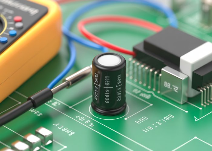
Capacitors are ubiquitous components in modern electronics, playing a crucial role in everything from power supplies to signal processing circuits. These seemingly simple devices possess a unique ability to store electrical energy, making them indispensable for a wide range of applications.
Understanding the fundamental principles governing their behavior, particularly their relationship with voltage, is paramount for anyone involved in circuit design, analysis, or troubleshooting.
Capacitors: The Unsung Heroes of Electronics
At its core, a capacitor is a passive electronic component consisting of two conductive plates separated by a dielectric material. This arrangement allows it to accumulate and store electrical charge when a voltage is applied.
The ability to store charge and release it when needed allows capacitors to perform various functions in a circuit, such as filtering unwanted noise, smoothing voltage fluctuations, and storing energy for later use. Their versatility makes them essential building blocks in nearly every electronic device we use today.
Why Voltage Behavior Matters
The voltage across a capacitor is not just a static value; it’s a dynamic quantity that changes over time in response to the current flowing into or out of the device. This dynamic behavior is what gives capacitors their unique functionality and makes understanding it so critical.
Consider these key reasons why understanding voltage behavior is crucial:
- Circuit Design: Proper selection of capacitor values and voltage ratings ensures optimal circuit performance and prevents component failure.
- Circuit Analysis: Accurately predicting voltage changes across capacitors is essential for understanding the overall behavior of a circuit.
- Troubleshooting: Recognizing abnormal voltage patterns can help diagnose faults and identify malfunctioning components.
Failing to account for the dynamic voltage characteristics of capacitors can lead to unpredictable circuit behavior, instability, or even catastrophic failures. A solid grasp of these principles is therefore essential for any electronics professional or enthusiast.
A Roadmap to Capacitor Mastery
This guide aims to provide a comprehensive exploration of voltage behavior in capacitors, covering the key concepts and principles necessary for effective circuit design and analysis.
We will delve into the fundamental relationship between capacitance, voltage, and charge, exploring how these parameters interact to determine the behavior of a capacitor in various circuit configurations.
Specifically, we’ll cover:
- The fundamental principles of capacitance and energy storage.
- The relationship between current and the rate of change of voltage.
- The charging and discharging phases, including the concept of the time constant.
- The importance of voltage ratings and dielectric breakdown.
- Capacitive reactance and phase shifts in AC circuits.
- Practical applications showcasing capacitor voltage characteristics.
By the end of this guide, you will have a solid understanding of how voltage behaves in capacitors and how to leverage this knowledge to design, analyze, and troubleshoot electronic circuits effectively.
Capacitors are ubiquitous components in modern electronics, playing a crucial role in everything from power supplies to signal processing circuits. These seemingly simple devices possess a unique ability to store electrical energy, making them indispensable for a wide range of applications.
Understanding the fundamental principles governing their behavior, particularly their relationship with voltage, is paramount for anyone involved in circuit design, analysis, or troubleshooting.
With a basic understanding of the crucial role that capacitors play, let’s dive into the fundamental principles that govern their behavior. We begin by examining the concept of capacitance itself and how it enables these components to store energy.
Capacitors 101: Energy Storage Explained
At its core, a capacitor’s functionality revolves around its ability to store electrical charge. This ability, known as capacitance, is the defining characteristic of these components and the key to their diverse applications.
Defining Capacitance
Capacitance, denoted by the symbol ‘C’, quantifies a capacitor’s capacity to store electrical charge for a given voltage. Think of it as the "size" of the capacitor’s "charge tank." The larger the capacitance, the more charge it can store at a specific voltage.
The Q = CV Relationship
The relationship between charge (Q), capacitance (C), and voltage (V) is elegantly expressed by the equation:
Q = CV
Where:
- Q represents the amount of electrical charge stored in Coulombs.
- C represents the capacitance in Farads.
- V represents the voltage across the capacitor in Volts.
This simple yet powerful equation governs the fundamental behavior of capacitors. It tells us that the amount of charge stored is directly proportional to both the capacitance and the applied voltage.
Doubling the voltage doubles the charge stored. Doubling the capacitance also doubles the charge stored.
Understanding this relationship is critical for analyzing and designing circuits involving capacitors.
Storing Energy in an Electric Field
But how does a capacitor actually store charge? The answer lies in the electric field created between its conductive plates.
When a voltage is applied across the capacitor, electrons accumulate on one plate (making it negatively charged) and are depleted from the other plate (making it positively charged). This separation of charge creates an electric field between the plates.
It is this electric field that stores the electrical energy. The stronger the electric field, the more energy is stored. The dielectric material between the plates enhances the electric field and prevents the charges from directly flowing between the plates, which would discharge the capacitor.
The capacitor holds onto this stored energy, ready to release it when the circuit demands.
The Unit of Capacitance: The Farad (F)
Capacitance is measured in Farads (F), named after the renowned scientist Michael Faraday. One Farad is defined as the capacitance required to store one Coulomb of charge at a potential difference of one Volt.
In practice, one Farad is an extremely large unit. Most capacitors used in electronic circuits have capacitances in the microfarad (µF), nanofarad (nF), or picofarad (pF) range.
- 1 µF = 10-6 F
- 1 nF = 10-9 F
- 1 pF = 10-12 F
Understanding these units is crucial for interpreting capacitor values and selecting the appropriate components for your circuits.
The I = C(dV/dt) Equation: Current and Voltage Dynamics
Having established the fundamental relationship between charge, capacitance, and voltage (Q = CV), we now turn our attention to a more dynamic perspective. This involves understanding how current relates to the changing voltage across a capacitor. This relationship is the cornerstone of understanding how capacitors function in real-world circuits where voltages are rarely static.
Defining Current’s Role
Current, in its essence, is the flow of electric charge. More formally, it’s defined as the rate of change of charge with respect to time. This can be expressed mathematically as:
I = dQ/dt
Where:
- I represents the current in Amperes.
- dQ represents an infinitesimal change in charge.
- dt represents an infinitesimal change in time.
This equation tells us that current is not simply the presence of charge, but rather how quickly charge is moving past a given point.
The Key Formula: I = C(dV/dt)
The dynamic relationship between current and voltage in a capacitor is described by the equation:
I = C(dV/dt)
This equation is perhaps the most important for understanding how a capacitor behaves in a circuit. Let’s break down its components:
- I is the current flowing through the capacitor.
- C is the capacitance, a constant value for a given capacitor.
- dV/dt is the rate of change of voltage across the capacitor.
This equation reveals a crucial insight: the current through a capacitor is directly proportional to the rate of change of voltage across it. A rapid change in voltage will result in a large current, while a slow change in voltage will result in a smaller current.
Rate of Change is Key
It’s vital to understand that the current is related to the rate of change of voltage, not the voltage itself. A capacitor can have a substantial voltage across it, but if that voltage is constant (dV/dt = 0), then the current through the capacitor will be zero.
Consider a scenario where the voltage across a capacitor is held constant at 5V. According to the formula I = C(dV/dt), since dV/dt = 0, the current I = 0A.
In this instance, the voltage is non-zero, but the current flow is zero.
The Concept of "Blocking DC"
One of the most practical implications of the I = C(dV/dt) equation is the concept of "blocking DC." A DC (Direct Current) voltage is a constant voltage that does not change over time.
Since the derivative of a constant voltage is zero (dV/dt = 0), the current through a capacitor subjected to a DC voltage will eventually become zero once the capacitor is fully charged.
The capacitor effectively acts as an open circuit to DC signals. Initially, when a DC voltage is applied, there will be a charging current. But as the capacitor charges and the voltage across it reaches the applied DC voltage, the charging current ceases. The capacitor is now "blocking" the DC current.
This property makes capacitors invaluable in circuits where it is necessary to isolate AC signals from DC bias voltages, or to remove unwanted DC components from a signal. For example, in audio amplifiers, capacitors are used to block DC voltages from reaching the speakers, preventing damage and ensuring proper operation.
The relationship between current and the rate of voltage change provides a foundation for understanding capacitor behavior. But to truly grasp how capacitors function in circuits, we must explore what happens when they are actively charging and discharging. This dynamic dance of electrons reveals the practical implications of the I = C(dV/dt) equation.
Charging and Discharging: A Detailed Look
The Charging Phase: An Exponential Ascent
When a voltage source is connected to a capacitor through a resistor, the charging process begins. Electrons start flowing from the voltage source to one plate of the capacitor and away from the other, creating a charge imbalance.
This charge imbalance generates an electric field, resulting in a voltage across the capacitor. Initially, the voltage rises rapidly, as there is little charge stored. However, as the capacitor accumulates charge, the voltage increase slows down.
This slowdown is due to the increasing voltage opposing the incoming current. The charging process follows an exponential curve, gradually approaching the applied voltage.
Understanding the Discharging Phase: An Exponential Decay
When the voltage source is removed and the capacitor is connected to a resistive load, the stored charge begins to dissipate. The electrons flow from one plate of the capacitor, through the resistor, to the other plate, neutralizing the charge imbalance.
As the charge decreases, the voltage across the capacitor also decreases. Similar to the charging process, the discharging process follows an exponential curve. The voltage decays rapidly at first, then slows down as the charge diminishes.
Introducing the RC Circuit: The Resistor-Capacitor Partnership
The RC circuit, consisting of a resistor (R) and a capacitor (C) connected in series, is a fundamental building block in electronics. It plays a crucial role in shaping voltage and current waveforms.
The resistor limits the current flow during charging and discharging, influencing the rate at which the capacitor charges or discharges. The combination of resistance and capacitance determines the circuit’s time constant.
The Time Constant (τ = RC): Defining the Pace of Change
The time constant, denoted by the Greek letter tau (τ), is a critical parameter that governs the speed of charging and discharging in an RC circuit. It is defined as the product of the resistance (R) in ohms and the capacitance (C) in farads:
τ = RC
The time constant represents the time it takes for the capacitor voltage to reach approximately 63.2% of its final value during charging, or to discharge to approximately 36.8% of its initial value.
After one time constant (1τ), the capacitor voltage reaches 63.2% of its maximum value during charging. After two time constants (2τ), it reaches 86.5%, and so on. After approximately 5 time constants (5τ), the capacitor is considered to be fully charged (or fully discharged).
Ohm’s Law: The Current Limiter
The resistor in the RC circuit plays a crucial role in limiting the current flow during charging and discharging. According to Ohm’s Law (V = IR), the current through the resistor is directly proportional to the voltage across it and inversely proportional to its resistance.
During charging, as the capacitor voltage increases, the voltage across the resistor decreases, which in turn limits the charging current. Similarly, during discharging, the resistor limits the discharge current, preventing a rapid and potentially damaging release of energy.
By carefully selecting the values of the resistor and capacitor, designers can control the charging and discharging characteristics of the RC circuit, tailoring it to specific applications.
The dance of charging and discharging, governed by the RC time constant, reveals the capacitor’s dynamic nature. However, this delicate balance can be disrupted if we neglect a critical specification: the voltage rating.
Voltage Rating and Dielectric Breakdown: Preventing Catastrophe
The voltage rating of a capacitor is arguably one of the most important parameters to consider when incorporating these components into electronic circuits. It represents the maximum voltage that the capacitor can safely withstand across its terminals without risking damage or failure.
Understanding the Voltage Rating
Think of the voltage rating as the capacitor’s breaking point. It’s a limit established by the manufacturer, based on the capacitor’s construction and the properties of its dielectric material.
Exceeding this limit can lead to a phenomenon known as dielectric breakdown, which has serious consequences.
The Perils of Exceeding the Voltage Rating
Dielectric breakdown occurs when the electric field within the capacitor becomes too strong for the dielectric material to handle. The dielectric, which normally acts as an insulator between the capacitor plates, effectively becomes conductive.
This leads to a cascade of undesirable effects:
-
Short Circuit: The most immediate consequence is often a short circuit within the capacitor. The insulating properties are lost, allowing a large current to flow directly between the plates.
-
Component Damage: The excessive current and heat generated during dielectric breakdown can cause significant damage to the capacitor itself. This can range from subtle performance degradation to catastrophic failure, such as bursting or melting.
-
Collateral Damage: A failing capacitor can also damage surrounding components in the circuit. The sudden surge of current or the release of energy can overload other parts, leading to further failures and potentially hazardous situations.
-
Safety Hazards: In some cases, dielectric breakdown can pose safety hazards, such as fire or electrical shock. This is especially true in high-voltage applications or when dealing with large capacitors that store significant amounts of energy.
Selecting the Right Capacitor: A Proactive Approach
Preventing dielectric breakdown is a matter of careful capacitor selection. Here’s a guideline:
-
Know Your Voltages: Accurately determine the maximum voltage that the capacitor will be subjected to in the circuit. This includes steady-state voltages as well as transient voltage spikes.
-
Consider a Safety Margin: Always choose a capacitor with a voltage rating significantly higher than the maximum expected voltage. A common rule of thumb is to use a capacitor with a voltage rating at least twice the maximum voltage. This "safety margin" provides protection against unforeseen voltage spikes or variations.
-
Understand the Application: The specific application of the capacitor can influence the required voltage rating. High-reliability applications or safety-critical systems may demand even larger safety margins.
-
Consult Datasheets: Always refer to the manufacturer’s datasheet for detailed specifications and recommendations regarding voltage ratings and operating conditions.
By understanding the importance of voltage ratings and implementing proactive selection strategies, engineers and hobbyists can prevent catastrophic failures and ensure the reliable operation of their circuits.
The dance of charging and discharging, governed by the RC time constant, reveals the capacitor’s dynamic nature. However, this delicate balance can be disrupted if we neglect a critical specification: the voltage rating. Now, let’s shift our focus from direct current to alternating current and explore how capacitors behave in a completely different environment.
Capacitors in AC Circuits: Reactance and Phase Shifts
Capacitors, which appear as open circuits to DC after being fully charged, exhibit a fascinating contrast when exposed to alternating current (AC). Unlike their behavior in DC circuits, capacitors readily allow AC current to flow. This fundamental difference stems from the constantly changing voltage in AC circuits, which continuously charges and discharges the capacitor. This continuous cycle creates the illusion of current flow through the capacitor.
The Curious Case of AC Current Flow
In a DC circuit, once a capacitor is charged, it blocks further current flow. The electric field between the plates reaches equilibrium, and no further charge accumulation occurs.
However, AC circuits are characterized by a continuously varying voltage. This means the capacitor is constantly charging and discharging, responding to the alternating polarity of the voltage source. This continuous charging and discharging cycle facilitates the movement of charge in the circuit, effectively allowing AC current to "pass" through the capacitor.
Capacitive Reactance (Xc): AC Opposition
While capacitors permit AC current to flow, they do offer a form of opposition, known as capacitive reactance (Xc). Reactance, analogous to resistance in a DC circuit, impedes the flow of current in an AC circuit. However, unlike resistance, reactance is frequency-dependent.
The formula for capacitive reactance is:
Xc = 1 / (2πfC)
Where:
- Xc is the capacitive reactance in ohms (Ω)
- f is the frequency of the AC signal in hertz (Hz)
- C is the capacitance in farads (F)
Frequency’s Influence
The formula reveals an inverse relationship between capacitive reactance and frequency. As the frequency increases, the capacitive reactance decreases, allowing more current to flow. Conversely, as the frequency decreases, the capacitive reactance increases, hindering current flow.
This frequency-dependent behavior makes capacitors valuable components in frequency-selective circuits, such as filters.
Phase Shift: A 90-Degree Lead
One of the most significant characteristics of capacitors in AC circuits is the phase relationship between voltage and current. In a purely capacitive circuit, the current leads the voltage by 90 degrees.
Visualizing the Shift
Imagine a sine wave representing the voltage across the capacitor. The current waveform will be another sine wave, but shifted 90 degrees to the left. This means the current reaches its peak value a quarter of a cycle before the voltage reaches its peak.
Implications of the Phase Shift
This phase shift has important implications in AC circuit analysis and design. It affects the power factor of the circuit and influences the behavior of more complex circuits containing both capacitors and inductors. Understanding this phase relationship is crucial for designing efficient and stable AC systems.
The dance of charging and discharging, governed by the RC time constant, reveals the capacitor’s dynamic nature. However, this delicate balance can be disrupted if we neglect a critical specification: the voltage rating. Now, let’s shift our focus from direct current to alternating current and explore how capacitors behave in a completely different environment.
Applications: Leveraging Capacitor Voltage Characteristics
Capacitors are not merely theoretical components confined to textbooks.
Their unique voltage characteristics make them indispensable in a wide array of practical applications, shaping the behavior of circuits in crucial ways.
Let’s explore some key examples, highlighting how these voltage properties are ingeniously leveraged.
Voltage Smoothing in Power Supplies
One of the most common and vital applications of capacitors is in voltage smoothing within power supplies.
Power supplies convert AC voltage from the mains to a stable DC voltage required by electronic devices.
However, this conversion process isn’t perfect; it often results in a residual AC component superimposed on the DC voltage, known as voltage ripple.
This ripple can interfere with the proper functioning of sensitive electronic circuits.
Capacitors step in as voltage stabilizers.
Placed in parallel with the load, they act as reservoirs of charge, charging up during the peaks of the voltage waveform and discharging during the troughs.
This charging and discharging action effectively filters out the ripple, producing a much smoother DC voltage output.
The size of the capacitor directly affects its smoothing capability. Larger capacitors can store more charge and, therefore, provide better ripple reduction.
Choosing the right capacitor value is crucial for optimal performance.
Signal Filtering in Audio Circuits
Capacitors also play a vital role in signal filtering, especially in audio circuits.
Their ability to block DC signals while allowing AC signals to pass is fundamental to this application.
Consider a scenario where you want to isolate the AC audio signal from a DC bias voltage.
A capacitor placed in series with the signal path will effectively block the DC component, allowing only the AC audio signal to pass through.
This is because the capacitor charges up to the DC voltage, effectively becoming an open circuit for DC, while the alternating nature of the AC signal allows it to continuously charge and discharge, thus "passing" the AC.
Furthermore, capacitors can be used to create frequency-selective filters.
By combining capacitors with resistors in different configurations (e.g., low-pass, high-pass, band-pass filters), you can design circuits that selectively attenuate or pass signals of certain frequencies.
For instance, a capacitor in series with a resistor can create a high-pass filter, allowing high-frequency signals to pass while blocking low-frequency signals.
The cutoff frequency of the filter, which determines the boundary between passed and blocked frequencies, is determined by the values of the capacitor and resistor.
These filtering capabilities are essential in audio systems for tasks such as removing unwanted noise, shaping the tonal characteristics of the audio, and separating different frequency bands.
FAQs: Understanding Capacitor Voltage
Here are some frequently asked questions to clarify key concepts from "Unlock Capacitor Voltage: The Ultimate Guide!".
What determines a capacitor’s voltage rating?
A capacitor’s voltage rating, also known as the working voltage, is the maximum DC voltage it can safely handle without dielectric breakdown. Exceeding this rating can damage the capacitor, leading to failure. The manufacturer specifies this voltage based on the capacitor’s design and materials.
Can a capacitor store voltage indefinitely?
Ideally, a capacitor would hold its voltage indefinitely. However, in reality, capacitors slowly discharge over time due to leakage currents within the dielectric material. The rate of discharge depends on the capacitor’s type, size, and the circuit conditions.
How does the voltage through a capacitor affect its energy storage?
The energy stored in a capacitor is directly related to the square of the voltage across it (E = 1/2 C V^2). Therefore, increasing the voltage through the capacitor significantly increases the amount of energy stored, but it must remain within the capacitor’s voltage rating.
Is it dangerous to touch a charged capacitor?
Yes, touching a charged capacitor can be dangerous. A charged capacitor stores electrical energy, and if touched, it can discharge through your body, potentially causing a painful shock. The severity of the shock depends on the capacitor’s voltage and capacitance. Always discharge capacitors before handling them.
So there you have it! Hopefully, this guide has cleared up any confusion about voltage through capacitor. Now go out there and build something awesome! I’m excited to see what you come up with.